
Four Fiber Patch Panel Routing Guidelines
By Eric Pearson, Pearson technologies
Requirements
During cable installation at patch panels, installers need to achieve conformity to the National Electrical Code (NEC). This article presents four guidelines that make practical conformity at patch panels possible.
The “NEC and Optical Fiber Cable and Raceway Rules” state:
“You must install equipment and cabling in a neat and workmanlike manner (NEC Section 770.24). One of the implications of this is the routing of your cables cannot interfere with access to equipment (NEC Section 770.21).”[1]
There can be conditions, such as increased cost or unavailable hardware, with priority higher than that of avoiding interference completely. Under such conditions, avoiding interference completely (i.e., ‘cannot’) may not be possible or practical. Instead, the goal becomes avoiding and/or minimizing interference.
Minimizing interference has two benefits: convenience in accessing ports and avoidance of reduced reliability. Reduced reliability occurs when a technician damages a patch cable while moving a cable to access equipment or a port. With such movement, there is a risk of damaging cables or interrupting signals.
Bend Radius Rule
Because fiber cable contains glass fiber, there are rules that govern the radii to which the cable can be bent. These rules result from the two limitations of transmission over glass. The first limitation is obvious: glass does not bend well, As a result, there is a minimum bend radius, below which the fiber will break. The second limitation results from the behavior of light in fiber: below a specific bend radius, optical power will escape from the fiber, resulting in reduced power delivered to the receiver.
These limitations result in the Rule:
· Do not violate either minimum bend radii,
This is a rule, not a guideline. Violation of bend radius reduces both system margin and cable reliability.
For most cables, the two rules are do not bend the cable below the appropriate minimum bend radii:
o For unloaded cables, the minimum is 10 times the cable diameter
o For cables loaded up to the maximum recommended installation load, the minimum is 20 times the cable diameter
Four Guidelines
Following four guidelines achieves of the goal of avoiding and/or minimizing interference:
1. Feed cable from both sides of the enclosure (‘side feeds’)
2. Feed cable from both top and bottom of the enclosure (top/bottom feeds)
3. Each cable exits its bundle as close as possible to the destination column or row without violating the bend radius rule, as indicated above.
4. For enclosures larger than 3U, cables exit the vertical or horizontal cable manager at the location or close to location of the destination port (bundle exit)
Four Scenarios
To demonstration these guidelines, this article presents four scenarios: a 3U enclosure, an enclosure larger than 3U, a 1U enclosure, and a 2U enclosure.
For a 3U enclosure, Guidelines 1 and 2 result in cable feed /paths at both sides and the top and bottom, as presented in Figure 1. This routing minimizes interference, as each vertical cable bundle passes over (i.e., ‘interferes with access to’) three ports.
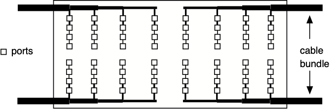
Figure 1: Left/Right and Top/Bottom Feeds
Routing from both sides of a 3U enclosure without routing from the top and bottom does not result in minimum interference, as each horizontal cable bundle passes over three ports (Figure 2).
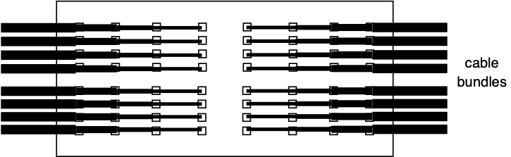
Figure 2: Left/Right Feed
Routing from only the top or bottom without routing from the sies does not minimize interference: such routing results in the vertical cable bundle passing over five ports. Routing from one side results in the horizontal cable bundle passing over seven ports.
If the number of rows or columns of ports is larger than those shown in Figure 1, the same guidelines apply. The number of ports ‘passed over’ (access interfered with) increases.
Routing cables from one column to a different column, as presented in Figure 3, results in interference with cables in the different column. In addition, such routing fails to comply with the requirement for ‘cabling in a neat and workmanlike manner’.
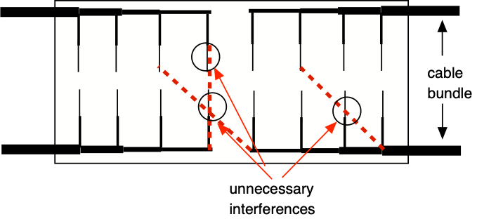
Figure 3: Feeding Across Columns
Routing cables in a 1U enclosure from the top or bottom results in no interference. Routing from both sides does not result in minimizing interference.
Routing cables in a 2U enclosure from the top and bottom results in no interference. Routing cables in a 2U enclosure from the top or bottom or from one or both sides results in some interference.
Examples
Figures 4to 9 illustrate aspects of the four rules. Figure 4 illustrates guidelines 1 and 4.
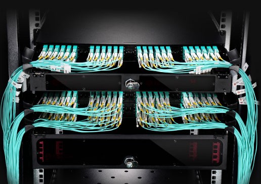
Figure 4: Example of Guidelines 1 and 4[2]
Figure 5 illustrates Guideline 4 (bundle exit). It does not illustrate Guideline 1, as cables feed from one side only. It does not illustrate Guideline 2, as cables feed from the bottom only.
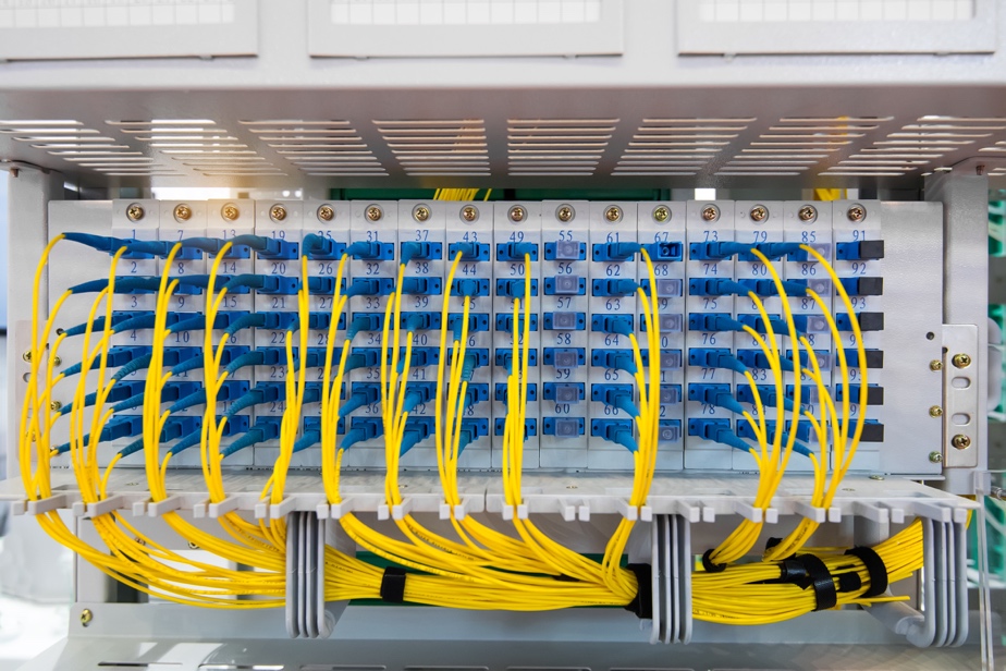
Figure 5: Example of Guideline 4
Figure 6 illustrates none of the guidelines. It illustrates right feed only. In the most severe instance of interference, the left cable pass over 23 ports. Note also potential violations of the bend radius rule at the six left--most ports.
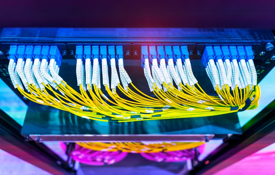
Figure 6: Example of No Guidelines
Figure 7 illustrates Guideline 1 (side feeds) but not Guideline 4 (bundle exit). Note that the cables to the two central columns pass over (interfere with) 11 ports.
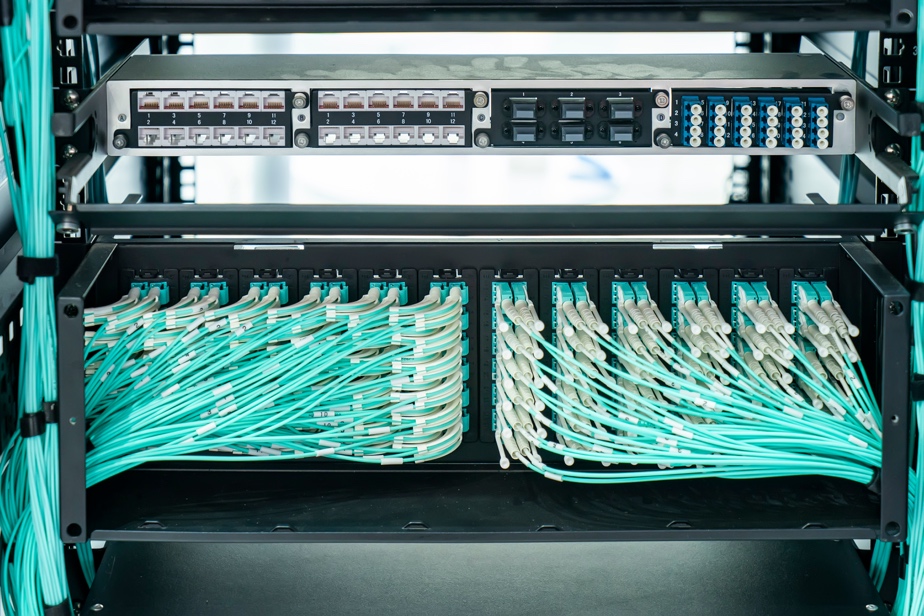
Figure 7: Example of Guideline 1
Figure 7 illustrates Guideline 2 (top and bottom feed) and Guideline 4 (bundle exit).
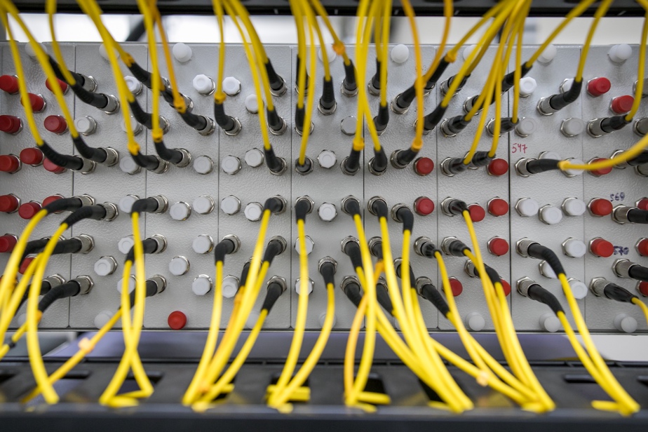
Figure 7: Example of Guideline 2
Figure 9 illustrates Guideline 1 (side feeds) and Guideline 4 (bundle exit).
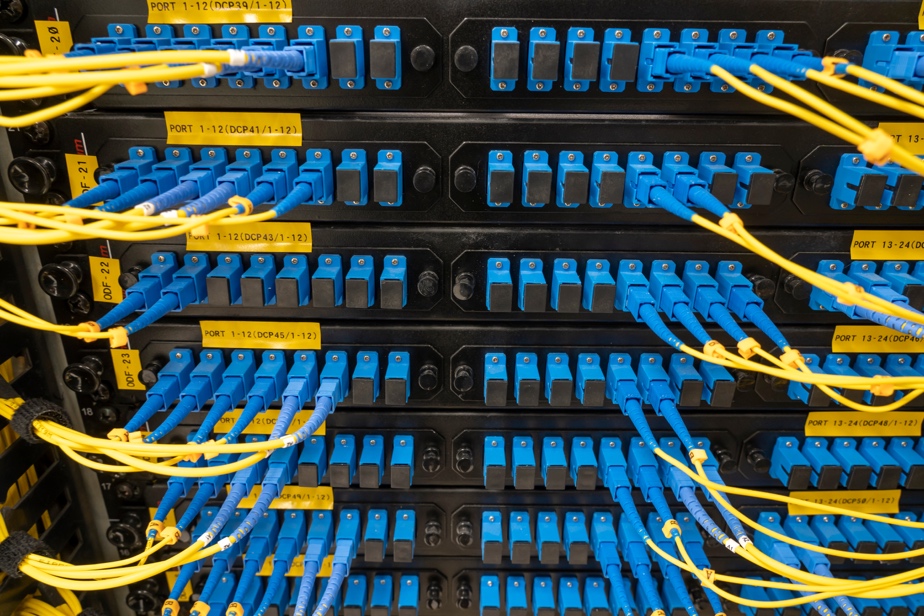
Figure 9: Example of Guideline 1 and Guideline 4
Figure 10 illustrates unknown guidelines. Comparison of Figures 3-7 to Figure 9 demonstrates that minimal interference and neatness result from following the four guidelines.
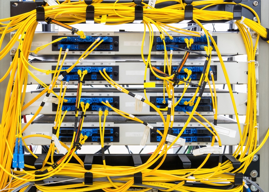
Figure 10: Example of Unknown Guidelines
Potential Consequence
Figures 3 to 9 illustrate examples of minimizing interference. Minimization has a potential consequence: a requirement for custom cable lengths for each port. Custom cable lengths can be avoided with multiple standard-length cables and storage of excess length within cable slack management systems. Such systems consist of a standard rack mounted enclosure or a storage box (Figure 11), both with internal bend radius control mechanism(s) (Figure 12).
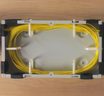
Figure 11: Slack Storage Box (Courtesy Amphenol)
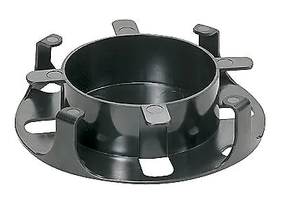
Figure 12: Bend Radius Insert (Courtesy Panduit Corporation)
Custom lengths can be achieved in 2 ways:
· Purchase cables in long lengths. Cut cables to required length resulting in two cables. Terminate the cut ends with splice on connectors (SOCs). SOCs are available as mechanical splice-on connectors (e.g., Unicam® from Corning) and fusion splice-on connectors (e.g., INNO). Both types are available from multiple manufacturers For a list of manufacturers, see: https://foa.org/foanl-2-21.html.
· Purchase custom lengths for each cable path
Conclusion
The primary goal of the guidelines is minimization of interference. Minimization of interference results in three benefits: compliance with the requirements of the NEC, improved convenience and increased reliability. A fourth benefit is avoidance of bend radius violation, as shown in Figure 6. Such violation can reduce system margin and cable reliability.
Eric R Pearson, CFOS/T/C/S/I, has 45 years of experience in fiber optic communications. Pearson Technologies Inc. provides installer training and certification, and technical support for fiber optic lawsuits. Contact Pearson Technologies at: fiberguru@ptnowire.com, www.ptnowire.com, www.fiberopticlawsuits.com, or 770-490-9991.
minimized interference at patch panels.docx
18 August 2022