Designing And Installing Optical LANs (OLANs)
Introduction
Centralized Cabling - Fiber to the Desk and Fiber To The Office
Passive Optical LANs
Designing And Installing Optical LANs (OLANs)
Testing OLANs
Introduction
Every network and every installation is different. Different sizes, number and types of users. Different physical layout, buildings, campuses and even metropolitan networks. Different equipment, locations and connections. As a result, it is only possible to give general guidelines for design, but it is the designer and installer who along with the network owner or manager who have responsiblilty for understanding the network technology and user situation to create a good network. So here is some general advice. We suggest you read the background material if you have not already.
Background Information
Additional links to FOA Guide pages are provided in the text.
The Development of LANs and Premises Cabling
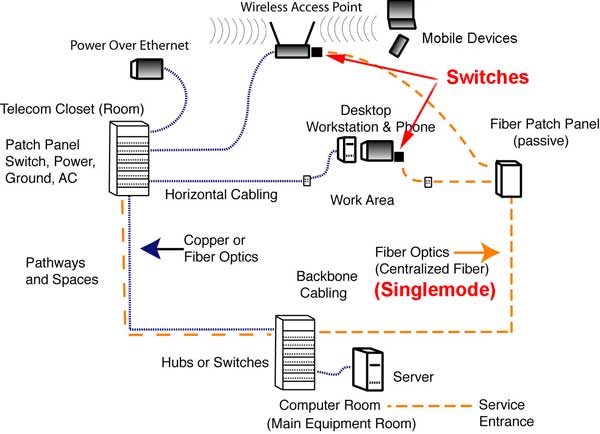
Here is the current day architecture of centralized fiber compared to normal structured cabling and the addition of WiFi access points. OLANs follow the same basic architecture as structured cabling but may have much longer links, depending on what type of fiber is used.
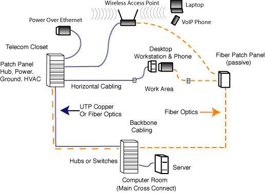
A network like this will often be built with fiber backbone if the distance required from the computer room to the telecom closet is over 100m (including risers and patchcords). The fiber may be run in innerduct since it is much smaller than bundles of copper cables. The number of cables to the desktop of wireless access points will typically be quite large with cabling standards calling for two UTP cables per user work area as a minimum. Thus there is usually a requirement for large cable trays to carry the bulky - and very heavy - UTP cables around the area where they will connect users. A typical installation looks like this:
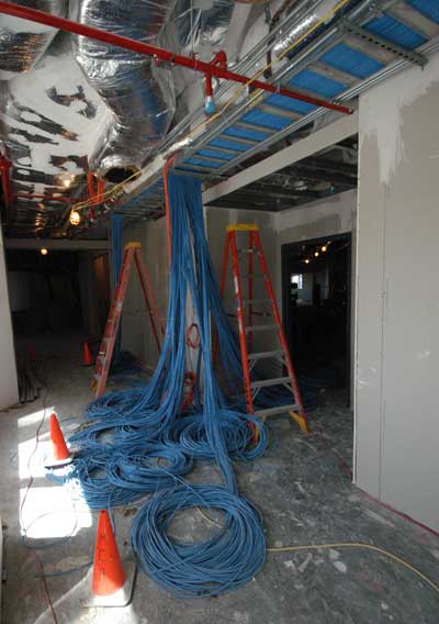
All those masses of copper cables can usually be replaced with a small fiber cable, often installed in a duct to protect it from harm by other workers.
Centralized fiber or fiber to the desktop (FTTD) uses a cabling diagram like the above but adds fiber to copper media converters to allow replacing UTP copper with fiber.
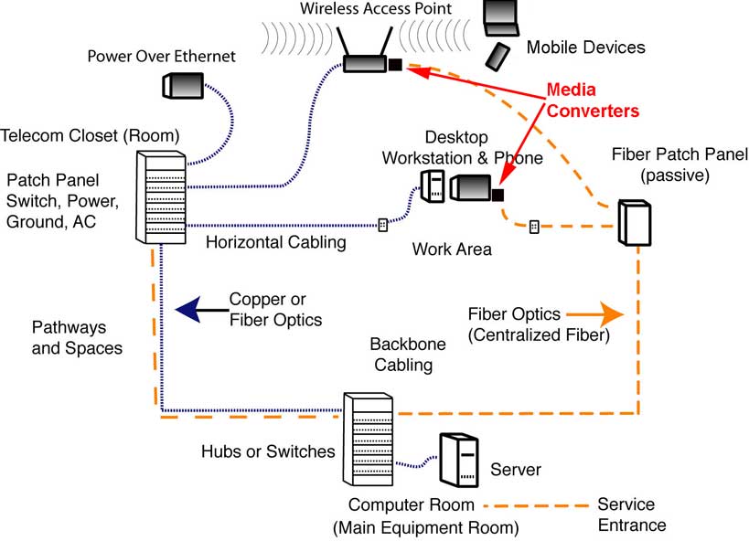
One of the reasons FTTD gained little acceptance was the cost of the conversion. Media converters are actually inexpensive, but the fiber ports on switches have always been very expensive. Several vendors suggested using local small switches in the media converters to spread the cost among several users, but that approach was hampered by a lack of equipment choice and specifications.
When centralized fiber is used, one needs only a small duplex fiber optic cable to the desktop. Most designs are based on multimode fiber and will use bend-insensitive fiber to allow smaller cables and reduce the effects of installation in tight spaces on fiber loss.
Fiber To The Office (FTTO)
Fiber to the office builds on centralized fiber and the idea of using local switches connecting many devices instead of just a media converter serving one device.
This approach works because this is a simple evolution of fiber to the home networks using so-called "point-to-point" (P2P) or "active Ethernet" architecture. FTTH systems are used in the millions, so the equipment needed has been highly developed and prices are much lower.
When FTTO is used, one needs a backbone cable to the patch panel serving multiple user areas and only a small duplex fiber optic cable to the desktop. Designs are based on singlemode fiber and will use bend-insensitive fiber to allow smaller cables and reduce the effects of installation in tight spaces on fiber loss. The switches are called "optical network terminals" (ONTs) in OLAN jargon. They can be powered locally or remotely using DC and sometimes composite cables (fiber and power conductors in one cable.)
The numbers of fibers needed in any given cable depend on the number of switches being used, as each switch needs 2 fibers back to the main switch in the computer room. The number of switches will be determined by the number of users or connected devices and the number of ports on each switch.
More On Centralized Cabling - Fiber to the Desk and Fiber To The Office
Passive Optical LANs (POLs)
Passive optical LANs use another similar cabling architecture but with a splitter serving work area ONTs (local switches.)
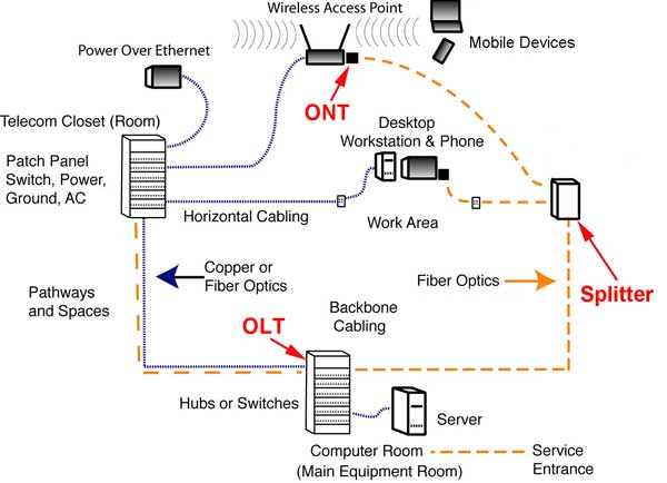
Passive optical LANs use a splitter to share one OLT connection in the main computer room with many users. Each splitter may have 32 ports and all or part may be connected to switches. A typical 32 port splitter may connect to 32 switches with 4 ports each to cover as many as 128 devices connected by simple Cat 5 patchcords. Each splitter has one fiber going to the OLT and one fiber going to each ONT since the PON system uses wavelength-division multiplexing to allow full duplex transmission over one fiber.
If a network is being upgraded, one may leave the existing horizontal drops (assuming they are Cat 5e or better) and install the ONTs in the current telecom room, using space and power available there.
More On Passive Optical LANs
Pathways And Spaces
OLANs require much less space than networks using structured cabling. The OLT for thousands of users takes up only a few feet of rack space. The cables to the splitters are very small. No telecom rooms are needed since there are no local switches and the splitters are very small, the size of a small book. Since there are no switches in telecom rooms, no power, grounds or AC are required.
If one is designing a building from new, not needing telecom rooms means much more usable space. However, in a upgrade, older telecom rooms will still exist and may be re-purposed after all the obsolete cables are removed. If a network is being upgraded, one may leave the existing horizontal drops (assuming they are Cat 5e or better) and install the ONTs in the current telecom room, using space and power available there.
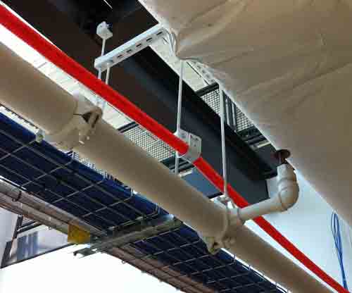
Many users prefer to run fiber optic cable in ducts for protection against damage by other workers in the area of the cable. Ducts may be lashed to current cable trays or J-hooks may be used.
Note: OLAN fiber cabling and network hardware is so small, it is quite possible to run the new cable plant in ducts lashed to the current cable plant, switchover to the new OLAN system and then remove all the obsolete copper (for recycling!) - allowing one to upgrade a system without any significant downtime.
Fiber And Cable
Centralized fiber using multimode fiber and media converters will generally use OM2, OM3 or OM4 fiber depending on the length of the runs and the speed of the network. OM3 is probably the best choice for most users as the additional bandwidth of OM4 fiber is not necessary. FTTO and passive OLANs need regular singlemode fiber (OS1 or OS2 - low water peak fiber). All premises fibers should be specified as bend-insensitive fibers (multimode and singlemode) to allow using smaller cable designs and tighter bends without excessive losses. Special cables that are used in FTTH are extremely small and easy to run in any environment, especially older buildings with little space for cables. Cables run around other cables can be specified with heavier jackets, armor or run in ducts.
Termination
Multimode fiber may be field terminated by using adhesive/polish connectors or prepolished/splice connectors. Singlemode fiber should only use prepolished/splice connectors or prefab cable assemblies (factory terminated) to meet network requirements for low reflectance connections. Reflectance can cause data transmission problems and must be minimized.
More On OLANs
Introduction
Centralized Cabling - Fiber to the Desk and Fiber To The Office
Passive Optical LANs
Designing And Installing Optical LANs (OLANs)
Testing OLANs
Training And Certification
FOA has an Optical LAN (OLAN) specialist certification (CFOS/L) with training available from FOA approved schools. Read more.
Here are more sources of information on Optical LANs.
The FOA YouTube Lecture 30, OLANs, Optical LANs

There is a new trade association focusing on passive optical LANs: APOLAN
Tellabs
Motorola/ARRIS
Cliff Walker's FTTO paper
3M on POLs
TE Connectivity on Optical LAN Solutions
Corning Cable Systems on Optical LAN Solutions
Table of Contents: The FOA Reference Guide To Fiber Optics
|