Testing FTTA -
Fiber To The Antenna
Note:
the techniques here are applicable to most short fiber
optic cables, including those used in premises cabling,
DAS (distributed antenna systems), etc.
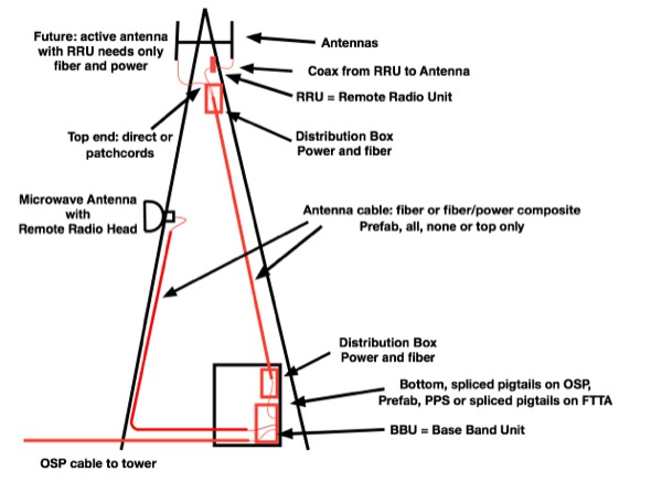
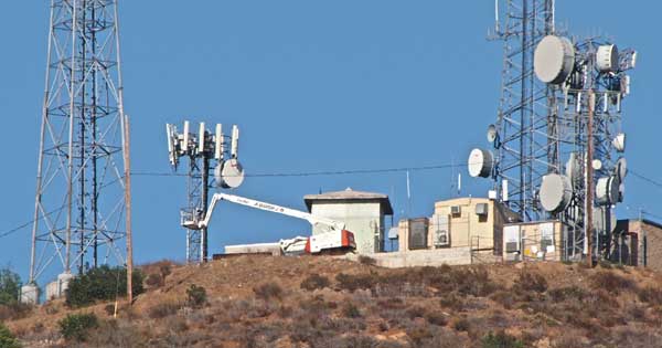
Successful installation of a fiber optic cable on a
cellular tower requires understanding the installation as
well as how to handle, inspect, clean and test the cables.
That includes the cable up the tower and the patchcords
used on the top and bottom of the tower to connect active
equipment.
Connector
Handling, Inspection And Cleaning
You must never assume that factory-installed
connectors are perfect or stay clean. Certainly they
should have been perfect when made and tested at the
factory, but the factory puts protective caps on the
connectors to ship them. We call those caps “dust caps”
and we say they are called “dust caps” because
they are usually full of dust.
So after you receive the cables, you should first remove
the dust caps and inspect the connector ferrule end face
for dust and scratches with a special fiber optic
inspection microscope. Then you clean them, inspect to
assure yourself the cleaning was done properly, then
test them. Likewise before you insert them into the
receptacles to mate with another connector, give them a
quick dry cleaning before insertion.
Never touch the end of the connector because the oils on
your finger will
Dirt is the #1 enemy of fiber optic connectors because
it can cause loss and reflectance, even damage
connectors. Inspect every connector before you make a
connection with it. Check the connector and the
receptacle it will be plugged into as either or both may
be dirty. To get low loss and reflectance, one needs a
“perfectly clean” connector ferrule end face.
There are both simple optical microscopes and video
microscopes available to check fiber optic connectors.
The best magnification is 100-400X, with 200 perhaps the
best, as 400X tends to have a smaller field of view –
you would like to see some of the connector ferrule to
be able to judge it’s condition as well as the fiber.
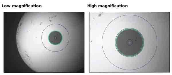
There
are three areas of inspection on a connector endface –
the fiber core zone where you must be most
discriminating, the fiber cladding zone and its epoxy
interface to the ferrule shown by dual zone lines, and
the connector ferrule. Since the ferrule is slightly
convex, it is the center of the ferrule that is most
important.
Video microscopes provide better views of the connector
endface plus they allow automatic analysis of the image.
Then the results can be stored for submission to the
user to verify the condition of the connector and kept
for future reference.
More
on connector inspection.
More
on cleaning fiber optic connectors.
Testing FTTA Cables
When dealing with either prefab or onsite terminated FTTA
cables, testing involves careful cleaning and inspection
with a microscope, insertion loss testing and in some
cases, OTDR testing.
Like any fiber optic cable and especially any prefab
cable, the tower cable should not be installed until it
has been tested to confirm that the cable is OK and has
not been damaged in shipment or handling. This also
includes the patchcords used on the tower. Even short
cables can cause major problems if they have been damaged
or are not clean.
Testing includes cleaning and inspecting the connectors,
checking continuity with a visual fault locator (VFL),
then do an insertion loss test with an optical loss test
set to determine if all fibers are OK. Recording this data
will help in the final test, after the cable has been
installed, by comparing losses before and after
installation to see if any damage was done during
installation.
Remember to always keep protective caps on all the
connectors except when cleaning, inspecting or testing.
After installation, the cable needs to be tested again to
ensure no damage was done to the cable during
installation. Insertion loss testing and perhaps OTDR
testing will be required.
Insertion Loss Testing
FTTA Cables
Insertion loss testing uses a test source like the
transmitter and an opitcal power meter like the receiver
to test a fiber the way it will be used in an operational
link. This is considered the most valid test for optical
fiber. The test diagram looks like this.
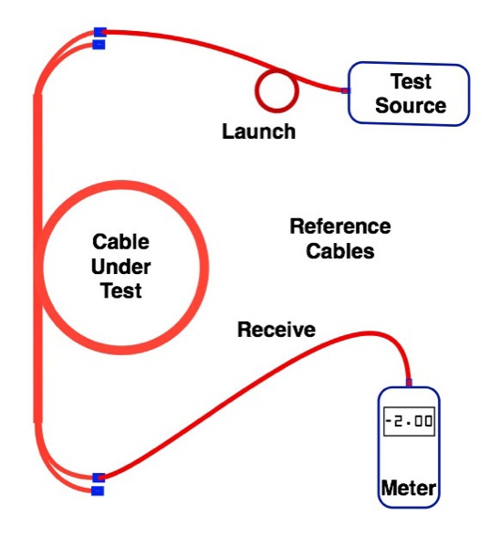
The power meter is used to calibrate the output of the
test source and launch cable, then measure the loss. The
launch and receive cables mate to the cable under test to
check the connections on both ends of that cable. This
test works well for the prefab cables that are waiting for
installation, but once the cable is installed up the
tower, this method is inconvenient so a different method
has been devised.
More
on insertion loss testing.
The
classical method of insertion loss testing of an installed
cable plant is not ideal for FTTA. This test would require
the tech on the top of the tower to have a source and
launch cable with him to connect to the cables. That is
very inconvenient and dangerous.
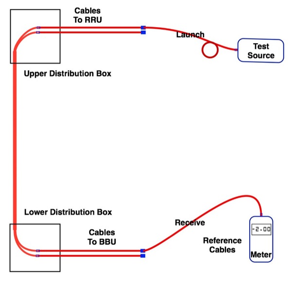
There is an alternative method you can use that is safer
and cuts test time almost in half. You have two fibers for
each RRU, each transmitting in opposite directions. By
putting a loopback on the two fibers at the top of the
tower, you can leave both testers on the ground and test
the two fibers at once.
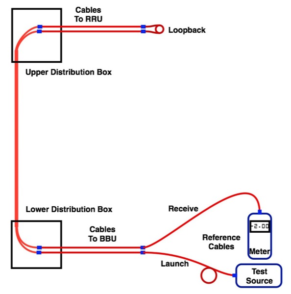
This method uses a loopback, basically a short cable that
plugs into the LC duplex connector in the upper
distribution box to “loop back” to the bottom of the tower
where the tech with the test instruments makes the
measurements. You can purchase loopbacks made for this
purpose. Then the tech at the top only has to be concerned
with cleaning the loopback and moving it to another pair
of fibers.
For practical reasons, having the loopback fairly long is
a good idea. If it is ~20m long, it can also be used with
a high-resolution OTDR to test the cables and record
traces for future reference.
OTDR Testing
The problem with using an OTDR on FTTA cables is most
cables are short for a typical OTDR’s limited resolution.
The best OTDRs for FTTA are those intended for premises
cabling or fiber to the home because they have higher
resolution. Set the OTDR to a short range and set the
shortest possible test pulse for highest resolution (5ns
will give a dead zone of ~4meters, among the shortest
resolutions available from today’s OTDRs.).
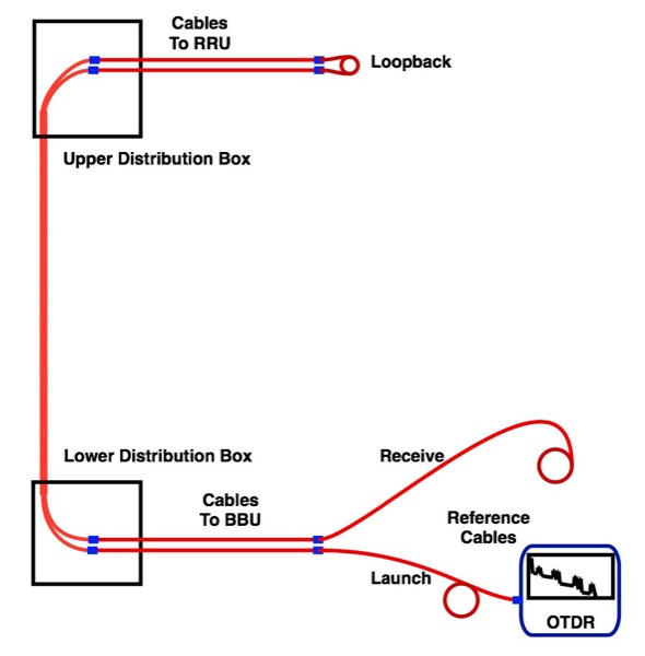
Loopback testing works for OTDRs also as long as the
loopback has a fiber length longer than the resolution of
the OTDR. Here we show using an OTDR with a launch cable
connected to one pair of a duplex link, a loopback
inserted at the top of the tower (a loopback is a ~20m
cable with connectors on each end, coiled up so the tech
at the top can plug it into the fiber pair under test),
then there is a receive cable at the other end of the
looped-back fibers. If testing bi-directionally, move OTDR
to end of the receive cable and take new trace.
When analyzing OTDR traces with such short cables, the
short patchcords may not be resolved, but instead the
reflectance of the connectors will be overlapping and
cause the traces to be harder to analyze.
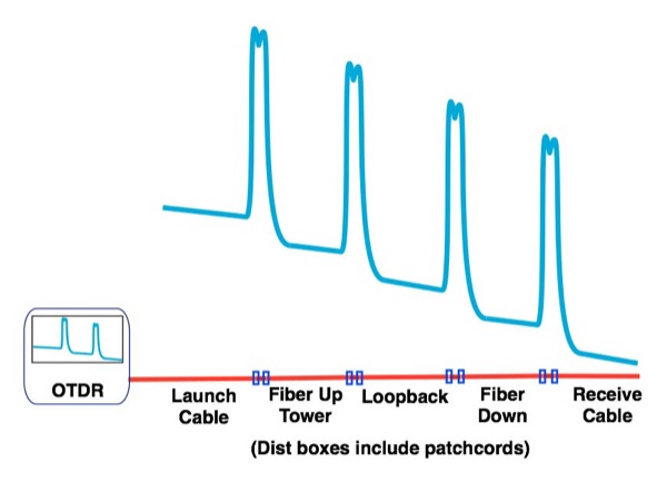
Schematic of OTDR trace
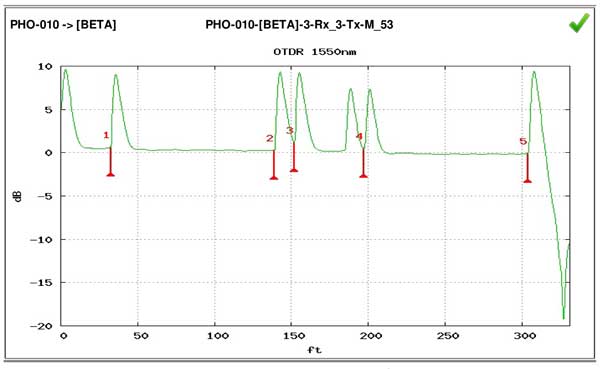
Actual OTDR trace of tower cable in loopback without
receive cable so the end connector cannot be measured.
While this makes it harder to find which connectors are
bad, it does not prevent the OTDR from making
measurements. One test is to measure the end-to end loss
of the cable using the OTDR by placing the OTDR markers as
shown.
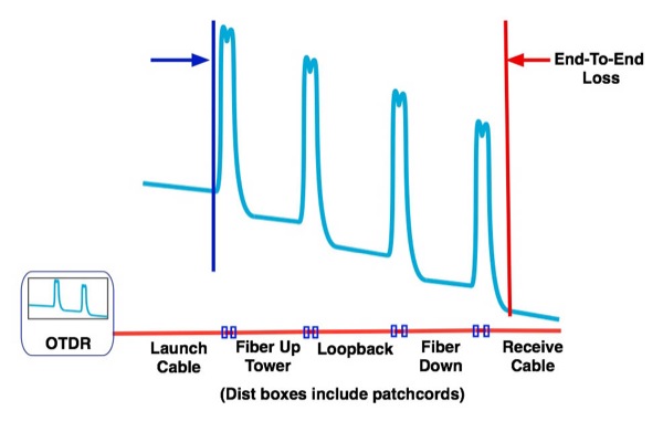
This measures the loss of all connectors and fiber,
although the loss of the fiber is probably too small on
such a short cable to make a significant contribution to
the loss.
There is another way to make this measurement that can be
more accurate. Use the "least squares" or "LSA" function
of the OTDR for making the test. LSA is not intended to be
used for a cable plant test but it works well for this
test. Here is the diagram for a cable test using LSA:
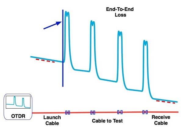
Place the marker at the beginning of the cable. Use the
LSA markers on the OTDR to set the limits for LSA at
either end of the cable (red dotted lines on the diagram)
and read the loss on the OTDR. The LSA option will
calculate the loss of the complete cable plant from end to
end with less uncertainty than the two point method, just
like when measuring the loss of a single connector or
splice.
One can also test just one of the cables, going up or
down. This is how to test the fiber going down. And you
can use the LSA function of the OTDR here in the same way.
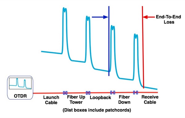
If you need to test the cables in both directions to
remove directional effects, simply disconnect the OTDR
from the launch cable and attach to the far end of the
receive cable and test in the reverse direction. (That's a
good reason to use launch and receive cables of the same
length. Also a long launch cable - longer than the cables
under test - will ensure that one does not get "ghosts in
the traces.)
More
on OTDR testing.
What Loss To Expect? The
Loss Budget
Calculating the loss budget is the best way to
estimate what loss we should be measuring. To calculate
the loss budget, we figure what is the maximum loss with a
normal installation. To begin, we need to know the
approximate length of the link and the number of
connectors and splices. For connectors, count the
connectors on each end as one each (we’ll mate them to
reference connectors when we test them) and each mated
pair used as a connection in the cable plant as one also.
Consider a simple FTTA cable shown as an example:
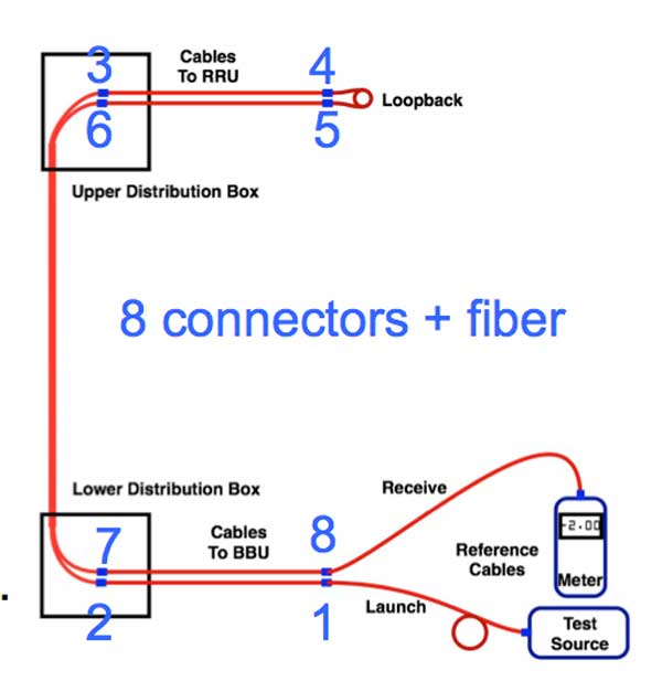
Link length: <0.1 km (~330 feet).
If it is SM fiber, it will have a minimal loss – the fiber
attenuation at 1310nm is only ~0.4dB/km so our <0.1km
link would have <0.04dB, basically ignorable. For MM
fiber at 3.5dB/km, it would be <0.3dB which is not
ignorable.
Connectors: 8, as noted in the diagram, including the ones
on the ends. Good connectors should be under 0.5dB,
typically 0.3dB, but we will use 0.5 for our loss budget,
so 8X0.5 = 4.0dB.
Splices: none
Add the connector losses to the fiber losses and we should
have:
SM: 0.04dB (fiber) + 4.0dB (connectors) = 4.04dB
MM: 0.3dB
(fiber) + 4.0dB (connectors) = 4.3dB
These numbers become “pass/fail” numbers for testing. When
you test the link, you should have less than those
calculated losses. If the loss is higher than that, you
may have problems with the cable installation or the
terminations, and should troubleshoot the installation –
beginning with cleaning. Remember these numbers are
estimates, so some judgement is needed.
Testing Equipment Optical
Power
Once the cables and equipment are installed, it may
be necessary to test the optical power of the system. To
measure the power output of a transmitter or the input
power of a receiver, use an optical power meter. Set it to
the wavelength being tested and the “dBm” or absolute
power range. Note the system must be turned on and set to
allow transmitter output. Also note the difference between
the source output and the receiver input on the same fiber
link is the loss in the cable plant.
Transmitter Power
The amount of light coupled into a fiber by a
source is measured by attaching a patchcord to the source,
either a known good system patchcord or a reference test
cable. The cable used must have a connector that mates
with the transmitter and a fiber size the same as the
system cabling (50/125, 62.5/125 or SM) since the coupled
power is highly dependent on the core size of the fiber.
The meter connector adapter must be the same type as the
connector on the cable to allow connection.
Connect the meter, set the range on dBm to measure power
(dB is used for loss) and be sure to set the wavelength to
the wavelength of the source, as the meter’s calibration
will be different due to the wavelength sensitivity of its
detector! Measure the power and record the results.
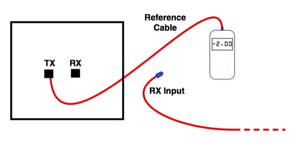
Receiver Power
Receiver power is measured by removing the cable
connected to the receiver input and connecting it to the
power meter.
Set the meter range on dBm or watts as appropriate and be
sure to set the wavelength to the wavelength of the
source, as the meter’s calibration will be different due
to the wavelength sensitivity of its detector!
Measure the power and record the results.
A Final Reminder
(Warning?)
FTTA installation involves work that is dangerous and for
which crews need specialized training and certification
plus specialized equipment made for this job. The danger
includes climbing towers, raising large cables up the
towers, working on the top of the towers to install and
test the cable, and something many forget, working around
sources of RF energy from the antennas that may be subject
to FCC regulation.
Follow
all applicable rules and use the proper personal safety
equipment!
More On Fiber For
Wireless
FTTA- Fiber To The
Antenna
Testing FTTA
Fiber
DAS - Distributed
Antenna Systems
Small Cells
WiFi
- Premises Wireless
Comparing
WiFi, Small Cells and DAS.
FOA
Guide Table of Contents.
|