Jump to:
Fiber Trivia Although glass optical fibers are made of a material that everyone assumes is fragile, it's ultra pure glass is actually quite flexible and 3 times stronger than steel and 6 times stronger than titanium according to the largest manufacturer of optical fiber, Corning.
1300 or 1310nm? Fiber is filled with jargon that is traditional and often obtuse in meaning. The 1300/1310 issue goes back to the beginning. AT&T's long-wavelength lasers were statistically centered around 1310nm (but varied from 1290-1330 or more) so they adopted the 1310nm nomenclature. LEDs with a wider and more varied spectral output (~1260-1350nm with spectral widths of 60-150nm depending on the construction) became known as 1300nm devices. When NBS (now NIST) created a calibration standard for power meters, they used 850, 1300 and 1550nm so meter calibration is usually at those wavelengths, although some manufacturers offer both 1300 and 1310 or call it 1300/1310 because it is an irrelevant difference in calibration.
Also
see FOA
Lecture 60 How Fiber Works (video)
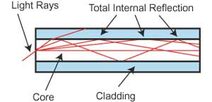
Total
Internal Reflection More
on total internal reflection in optical fiber.
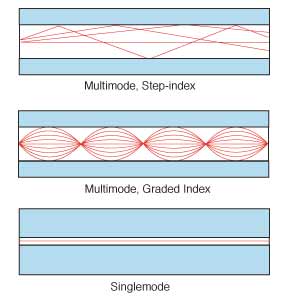
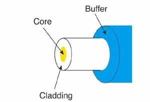
Graded Index Multimode Fiber Graded index multimode fiber uses variations in the composition of the glass in the core to compensate for the different path lengths of the modes. It offers hundreds of times more bandwidth than step index fiber - up to about 2 gigahertz. Two types are in use, 50/125 and 62.5/125, where the numbers represent the core/cladding diameter in microns. Graded index (GI) fiber has a range of materials in the core which are chosen to minimize modal dispersion caused by different path lengths of different modes being transmitted down the fiber. The core index profile is curved - a parabola to be exact - with lower index glass on the outside of the core. The lower index glass transmits the higher angle light rays (called high order modes) faster than the lower index glass near the center of the core.  The index profile of the core of multimode GI fiber is not continuous, which is hard if not impossible to manufacture, but is in steps, from hundreds of steps to thousands depending on the fiber design and manufacturing process. As a mode of light goes through each step, it is bent slightly until it is reflected back toward the core of the fiber. To help visualize the layers in the fiber, consider a Fresnel lens, a "flat" lens made from annular rings of glass that approximate a regular lens. These lenses are used in lighthouse lights like this one: 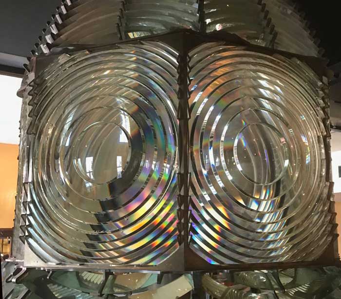
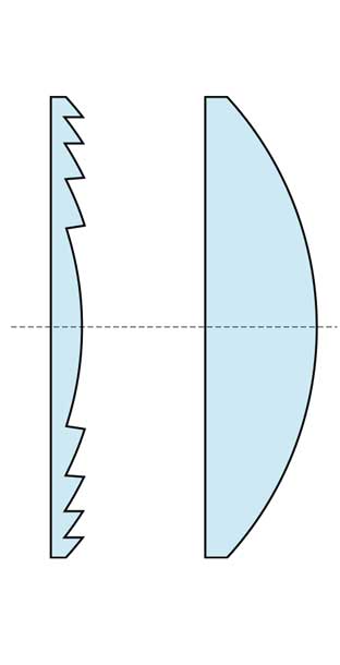 A Fresnel lens like this one used in a lighthouse is a flat lens made of segments of a regular lens. Index of refraction is related to the speed of light in the fiber; N=C/V, so a higher index of refraction indicates that light travels at a slower speed (V) relative to the speed of light in a vacuum (C.) Since the light is going into a lower index of refraction material in the outside of the core, it speeds up compared to the speed at the center of the core. By carefully designing and manufacturing the fiber, you can get the average speed of a higher-order mode approximately the same as the modes going straight down the fiber, reducing modal dispersion.  While the majority of graded-index fiber is all glass, there are some GI POF fibers also. Singlemode Fiber Singlemode fiber shrinks the core down so small that the light can only travel in one ray or mode, hence the name singlemode.  Since there is only one mode, there is no problem with modal dispersion and the choice of core material can reduce chromatic dispersion (see below) which increases the bandwidth to almost infinity - but it's practically limited to about 100,000 gigahertz - that's still a lot! Singlemode fiber has a core diameter of 8-10 microns, specified as "mode field diameter," the effective size of the core, and a cladding diameter of 125 microns. Specialty Fibers have been developed for applications that require unique fiber performance specifications. Erbium-doped singlemode fibers are used in fiber amplifiers, devices used in extremely long distance networks to regenerate signals. Fibers are optimized for bandwidth at wavelengths appropriate for DWDM systems or to reverse chromatic dispersion. This is an active area of fiber development. Fiber comes in two types, singlemode and multimode. Except for fibers used in specialty applications, singlemode fiber can be considered as one size and type. If you deal with long haul telecom or submarine cables, you may have to work with specialty singlemode fibers. 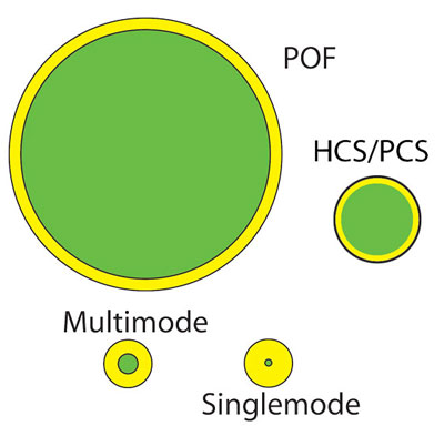
Relative sizes of all fibers 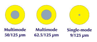
Comparison of core/cladding sizes Here is another way to look at fiber - The Optical Fiber Family Tree 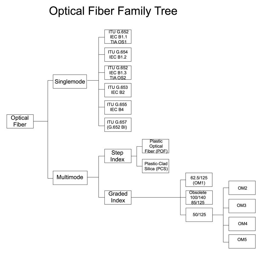 For information on what all the different designations mean, see the table below or go here. Multimode fibers originally came in several sizes, optimized for various networks and sources, but the data industry standardized on 62.5 core fiber in the mid-80s (62.5/125 fiber has a 62.5 micron core and a 125 micron cladding. It's now called OM1 standard fiber.) Recently, as gigabit and 10 gigabit networks have become widely used, an old fiber design has been revived. 50/125 fiber was used from the late 70s with lasers for telecom applications before singlemode fiber became available. 50/125 fiber (OM2 standard) offers higher bandwidth with the laser sources used in the gigabit LANs and can allow gigabit links to go longer distances. Newer OM3 or laser-optimized 50/125 fiber today is considered by most to be the best choice for multimode applications. OM4 fiber is a higher bandwidth fiber for 10G+ networks. OM5 is wideband multimode fiber optimized for wavelength division multiplexing with VCSELs in the 850-950nm range. To identify the types of fiber in a cable, there are standardized color codes for the cable jacket covered under TIA-598. Here is more information on color codes for cables and connectors.
CAUTION: You cannot mix and match fibers! Trying to connect singlemode to multimode fiber can cause 20 dB loss - that's 99% of the power. Even connections between 62.5/125 and 50/125 can cause loss of 3 dB or more - over half the power. More on mismatched fibers. Fiber Specifications The usual fiber specifications are size (core/cladding diameter in microns), attenuation coefficient (dB/km at appropriate wavelengths) and bandwidth (MHz-km) for multimode fiber and chromatic and polarization-mode dispersion for singlemode fiber. While manufacturers have other specs for designing and manufacturing the fiber to industry standards, like numerical aperture (the acceptance angle of light into the fiber), ovality (how round the fiber is), concentricity of the core and cladding, etc., these specs do not generally affect users who specify fibers for purchase or installation. Here is more information on testing fiber specifications. Some fibers have been designed to be much less sensitive to bend-induced losses. These "bend-insensitive" fibers are designed for use as patchcords or in tight premises appplications where regular fibers would suffer losses. Here is more information on bend-insensitive fibers. Attenuation The primary specification of optical fiber is the attenuation. Attenuation means a loss of optical power. The attenuation of an optical fiber is expressed by the attenuation coefficient which is defined as the loss of the fiber per unit length, in dB/km. 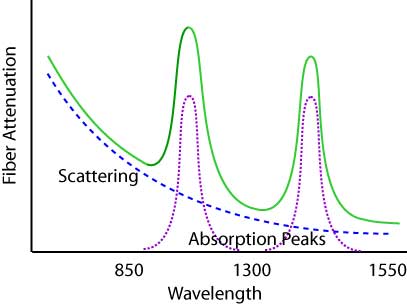 The attenuation of the optical fiber is a result of two factors, absorption and scattering. The absorption is caused by the absorption of the light and conversion to heat by molecules in the glass. Primary absorbers are residual OH+ and dopants used to modify the refractive index of the glass. This absorption occurs at discrete wavelengths, determined by the elements absorbing the light. The OH+ absorption is predominant, and occurs most strongly around 1000 nm, 1400 nm and above1600 nm. The largest cause of attenuation is scattering. Scattering occurs when light collides with individual atoms in the glass and is anisotropic. Light that is scattered at angles outside the numerical aperture of the fiber will be absorbed into the cladding or transmitted back toward the source Scattering is also a function of wavelength, proportional to the inverse fourth power of the wavelength of the light. Thus if you double the wavelength of the light, you reduce the scattering losses by 2 to the 4th power or 16 times. For example, the loss of multimode fiber is much higher at 850 nm ( called short wavelength) at 3 dB/km, while at 1300 nm (called long wavelength) it is only 1 dB/km. That means at 850 nm, half the light is lost in 1 km, while only 20% is lost at 1300 nm. Therefore , for long distance transmission, it is advantageous to use the longest practical wavelength for minimal attenuation and maximum distance between repeaters. Together, absorption and scattering produce the attenuation curve for a typical glass optical fiber shown above. Fiber optic systems transmit in the "windows" created between the absorption bands at 850 nm, 1300 nm and 1550 nm, where physics also allows one to fabricate lasers and detectors easily. Plastic fiber has a more limited wavelength band, that limits practical use to 660 nm LED sources. More: Wavelength Bands Used For Fiber Optic Transmission Bend-Insensitive (BI) Fibers When installing small fiber count cables indoors and routing patchcords around patch panels, fiber optic cables may be subjected to tight bends. This stress can cause bending losses in the fibers and even long term failure. Fiber manufacturers now offer bend-insensitive fibers, both singlemode and multimode, that are more tolerant of tight bending. One manufacturer even demonstrates the fiber by attaching it to wooden studs with a staple gun, a practice we strongly suggest you do not try its just for demonstrations! Bend insensitive fibers are a big advantage for patchcords or whenever fibers are subjected to stress, but manufacturers should be consulted to see if these fibers require special techniques for splicing, termination or testing. More on BI fibers. Low Water Peak Fibers Low water peak fiber results from careful manufacturing of singlemode fiber to reduce the water in the fiber (in the form of OH- ions) that causes higher spectral attenuation at around 1244 and 1383 nm. At the water peaks, legacy fibers may have attenuation coefficients around 2 dB/km while low water peak fibers may be as low as 0.4 dB/km. 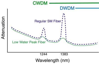 With the development of low water peak fibers, the possibility of transmission in the complete spectral range from 1260 to 1675 nm has been made possible. Coarse wavelength division multiplexing (CWDM) uses lasers over this entire wavelength range while dense wavelength division multiplexing uses more closely spaced lasers at wavelengths above 1500 nm. Modal Effects on Multimode Fiber Attenuation In multimode fibers, some light rays travel straight down the axis of the fiber while all the others wiggle or bounce back and forth inside the core. In step index fiber, the off axis rays, called "higher order modes" bounce back and forth from core/cladding boundaries as they are transmitted down the fiber. Since these high order modes travel a longer distance than the axial ray, they are responsible for the modal dispersion that limits the fiber's bandwidth. In graded index fiber, the reduction of the index of refraction of the core as one approaches the cladding causes the higher order modes to follow a curved path that is longer than the axial ray (the "zero order mode"), but by virtue of the lower index of refraction away from the axis, light speeds up as it approaches the cladding and it takes approximately the same time to travel through the fiber. Thus the "dispersion" or variations in transit time for various modes is minimized and bandwidth of the fiber is maximized. However, the fact that the higher order modes travel farther in the glass core means that they have a greater likelihood of being scattered or absorbed, the two primary causes of attenuation in optical fibers. Therefore, the higher order modes will have greater attenuation than lower order modes, and a long length of fiber that was fully filled (all modes had the same power level launched into them) will have a lower amount of power in the higher order modes than will a short length of the same fiber. 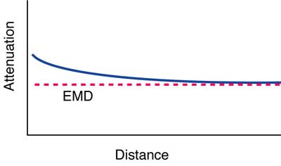 This change in "modal distribution" between long and short graded-index fibers is described as a "transient loss", and can make significant differences in the attenuation measurements one makes with the fiber, depending on the characteristics of the source. Transient loss not only changes the modal distribution, it changes the effective core diameter and numerical aperture also which can affect the losses of terminations or splices. The term "equilibrium modal distribution" (EMD) is used to describe the modal distribution in a long fiber which has lost most of the higher order modes. A "long" fiber is one in EMD, while a "short" fiber has all its initially launched higher order modes. Modal conditions in the fiber can greatly affect measurements of the loss of the fiber and any terminations or splices associated with it. Various methods have been used to control modal conditions to make measurements more repeatable. These are discussed in the chapter on testing. Modal Effects on Singlemode Fiber Attenuation While the heading may sound contradictory, singlemode fiber can transmit multiple modes for short distances, perhaps as long as 100 meters. This generally occurs with coupled power from lasers or after a connector or splice. To prevent multimode effects, one uses a mode filter made by a small loop of the fiber whenever making measurements with singlemode fibers. Dispersion in Multimode and Singlemode Fiber Dispersion refers to the widening or spreading of pulses of light as they travel down an optical fiber. Dispersion is one of the factors that limits the bandwidth of a fiber link along with the bandwidth of the transmitter source. Dispersion has several causes that are described below.  Bandwidth Multimode fiber's information transmission capacity is limited by two separate components of dispersion: modal and chromatic. Modal dispersion comes from the fact that the index profile of the multimode fiber isn't perfect. The graded index profile was chosen to theoretically allow all modes to have the same group velocity or transit speed along the length of the fiber. By making the outer parts of the core a lower index of refraction than the inner parts of the core, the higher order modes speed up as they go away from the center of the core, compensating for their longer path lengths. 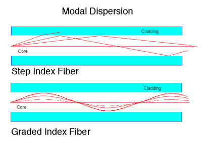 In an idealized fiber, all modes have the same group velocity and no modal dispersion occurs. But in real fibers, the index profile is a piecewise approximation and all modes are not perfectly transmitted, allowing some modal dispersion. Since the higher order modes have greater deviations, the modal dispersion of a fiber (and therefore its laser bandwidth) tends to be very sensitive to modal conditions in the fiber. Thus the bandwidth of longer fibers degrades nonlinearly as the higher order modes are attenuated more strongly. The concern for dispersion in multimode fibers today focuses on 850 nm systems using VCSELs, vertical-cavity surface-emitting lasers, the most practical source for high speed links. As Ethernet LAN and Fibre Channel and other data center links have gotten faster, multimode fiber has been optimized for those applications over a few hundred meters of multimode fiber. Thus multimode fiber bandwidth performance has been increasing from OM1 fiber to OM4 as shown in the table of fiber specifications above. Most fibers have been tested in the factory for bandwidth where the test source overfills the fiber, that is all modes are carrying light. Recent developments in laser-optimized fibers have caused new test methods to be developed, either limiting the modal fill of the fiber or using dispersion test methods that look at modes separately. Chromatic Dispersion 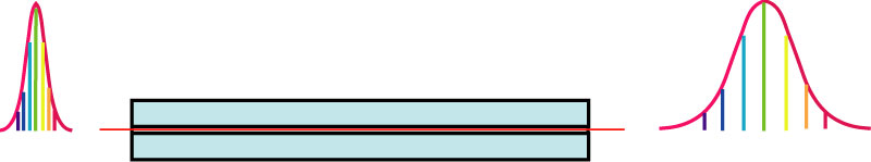 The second factor in fiber bandwidth, chromatic dispersion (CD), affects both multimode and singlemode fiber. Chromatic dispersion is caused by the fact that glass fibers transmit light of slightly different wavelengths at different speeds. The ratio of the speed of light in a medium to the speed in a vacuum defines the index of refraction or refractive index of the material. For optical fiber, the effective index of refraction is about 1.45, so the speed of light in glass is about 2/3 the speed of light in a vacuum. But the index of refraction, and thereby the speed of light in the fiber, is a function of the wavelength of light, the principle we all know from seeing a prism break light into a spectrum. Remember a prism spreads out the spectrum of incident light since the light travels at different speeds according to its color and is therefore refracted at different angles. The usual way of stating this is the index of refraction of the glass is wavelength dependent. Thus a carefully manufactured multimode graded index profile can only be optimized for a single wavelength, usually near 850 or 1300 nm, and light of other colors will suffer from chromatic dispersion. Even light in the same mode will be dispersed if it is of different wavelengths. 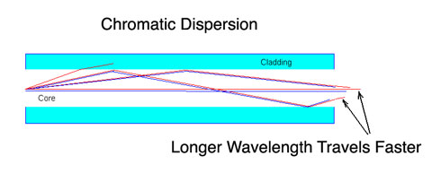 Chromatic dispersion is a big problem in multimode fiber with LED sources, which have broad spectral outputs, unlike lasers which concentrate most of their light in a narrow spectral range. Early high speed systems like FDDI at only 100 Mb/s but based on LEDs at 1300 nm, suffered such intense chromatic dispersion that chromatic dispersion was as large a factor as modal dispersion and transmission was limited to only two km of 62.5/125 fiber. Newer high speed multimode systems use fiber optimized for 850 nm VCSEL sources where modal dispersion is the main consideration (OM3 and OM4 fibers.) Dispersion in Singlemode Fiber Singlemode fiber only transmits one mode of light, so modal dispersion is not an issue. Chromatic dispersion however also affects long links in singlemode systems, even with lasers, so fiber and sources are optimized to minimize chromatic dispersion in the long distance links. As singlemode systems have become longer and faster, another dispersion factor has become important, polarization mode dispersion (PMD). PMD occurs because of the speed differences in polarized light propagating in the fiber. What Causes Chromatic Dispersion? There are two factors that cause chromatic dispersion in singlemode fibers: material dispersion and waveguide dispersion. Material Dispersion 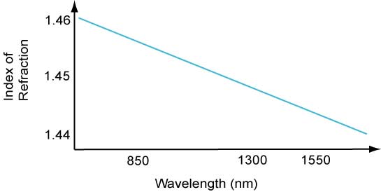 Material dispersion is caused by the variation of the index of refraction in a given material, glass in this case, over wavelength. Looking at the graph below, the variation of the index of refraction over the entire spectrum covered by fiber optics may seem small, only a few percent, but when you are dealing with very high speed pulses over very long distances it can add up. Waveguide Dispersion 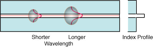 Waveguide dispersion is a bit more complex. In singlemode fiber, the wavelength of the light is not that much bigger than the core of the fiber and (well leave out the complex physics) as a result the light traveling down the fiber actually travels in an area that exceeds the diameter of the core, which we call the mode field diameter of the fiber. The mode field diameter is a function of the wavelength of the light, with longer wavelengths traveling in a larger mode field diameter. Thus part of the light is traveling in the geometric core of the fiber and part is traveling in the cladding. Since the core is made of a higher index of refraction glass than the cladding, the light in the cladding travels faster than the light in the core. Longer wavelengths have larger mode field diameters so they suffer more material dispersion. Engineered Dispersion in Fibers Material and waveguide dispersion have opposite variations with wavelength, so careful design of the fiber materials and index profiles allows the fiber to have a zero dispersion wavelength. On either side of that wavelength, dispersion increases. The importance of chromatic dispersion is a function of the application for the fiber. As a result, different SM fibers have been developed for the requirements of specific applications. The table of fiber types above shows the types of singlemode fibers currently in use and how they are optimized.
Dispersion Compensation As mentioned earlier, the dispersion characteristics of a fiber can be manipulated by the materials and design of the fiber. In fact, fibers can be made that have CD inverse to the typical fibers and of a greater magnitude. So a length of dispersion compensation fiber can be added to a link, usually at a repeater (optical amplifier) that reverses the CD of the fiber span before it. Such fibers tend to have high loss and bend sensitivity, so alternatively a dispersion compensator made from a specialized component called a bragg grating can be used, but it has a more limited use and higher cost. Chromatic Dispersion in the Cable Plant As with any other component, optical fiber performance parameters can vary from batch to batch, so a long concatenated cable plant with many different fibers will have a end-to-end chromatic dispersion which is an integration of the CD of all the individual fibers. Therefore fiber in long distance links will probably be tested for CD after installation or before upgrading a link to higher bit rate electronics. See the page on Testing. Polarization Mode Dispersion Polarization mode dispersion (PMD) in singlemode fiber is a bit more complex. Polarization is a phenomenon of light traveling in a medium as a wave with components at right angles. Some materials, like a glass optical fiber, have a different index of refraction for each of those components of the light wave, which is called birefringence. And a different index of refraction means light travels at a different speed, so in the simplest visualization, PMD in fiber looks like the drawing below, where each component of the polarized light travels at a different speed, causing dispersion. The magnitude of PMD in a fiber is expressed as this difference, which is known as the differential group delay (DGD) and called Δτ (delta Tau). 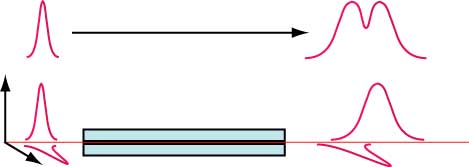 PMD is caused by the birefringence of the fiber which can be influenced by two factors, material birefringence and waveguide birefringence, similar to CD, but more complex. Waveguide birefringence is caused by geometrical variations in the fiber such as concentricity or ellipticity. Material birefringence is mainly caused by stress on the fiber. Waveguide Birefringence 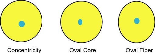 Material Birefringence 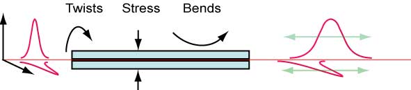 PMD is a complex issue in installed optical fiber. In a long concatenated fiber, each fiber can have different waveguide and material birefringence characteristics caused by the random characteristics of each fiber in the link and variations of the stress on the fiber. Variations are particularly noticeable in aerial fiber, where the PMD may vary considerably according to temperature and wind speed buffeting the fiber! PMD causes pulse broadening and/or jitter in the received electrical signal, potentially causing errors in the reception of the signals. Since the PMD can vary over time, an extra margin of 1 to 3 dB is often added to the power budget to accommodate variation in PMD. PMD is an important issue as data rates on long distance links increases to 40 Gb/s and 100 Gb/s. Unfortunately, there are no reliable compensation schemes for PMD, so the only solution is to test links to be upgraded for PMD using one or more of the standardized test methods. See the page on Testing. More on CD and PMD. Test Your Comprehension Table of Contents: The FOA Reference Guide To Fiber Optics |
|||||||||||||||||||||||||||||||||||||||||||||||||||||||||||||||||||||||||||||||||||||||||||||||||||||||||||||
|
|