
Optical
Splitters
Vladimir Grozdanovic
Introduction
The development of fiber optics often follows the conventions of electrical signals, for example the fiber amplifier mirrors an electronic amplifier. During the 1970s and 1980s there was research and development of an optical component that could separate or combine optical signals. The goal of the research was the development of a passive optical component, not an active one.
Early splitters were made by fusing fibers in high heat, twisting them together and melting them to combine all the fibers. By careful processing, couplers that were bidirectional were made. So a 2:2 coupler would take the signal from one fiber on one side and split it between the two fibers on the other side in either direction. Using this technique, one could put signals of two wavelengths on one fiber or send signals in both directions on a single fiber. The first fiber LAN, CodeNet from the mid-1980s used a 8:8 coupler to act like a hub connecting 8 users. Today couplers can be made fusing fibers, optics or using optical integrated circuits.
Today, the mass use of passive optical splitters is in passive optical networks, PON FTTx and OLAN networks (PON splitter or fiber optic coupler). An optical splitter is a passive bidirectional element, which is used to connect a large number of subscribers/ONUs to an OLT. It is one of the most important elements of all FTTx PON and OLAN networks. In downstream, the optical splitter has the function of a splitter or signal divider allowing multiple users to . In upstream, the optical splitter has the function of a combiner of multiple signals into one fiber.
Types of Optical Splitters
There are a number of different classifications of optical splitters.
According to the method of production of optical splitters, they are divided into two groups:
FBT (Fused Biconical Taper) splitters. They are created by the fusion of optical fibers (two or more fibers together). They are easy to produce and cheap. The maximum number of splits is 32 but they can be made with multiple inputs and outputs. Temperature has a significant effect on IL (Insertion Loss), FBT splitters have a working temperature range from - 5 to + 75 oC.
PLC (Planar Lightwave Circuit) splitters. A special technology is used for the production of silica or other materials. The optical splitting is done by a solid state waveguide whose task is to separate the light. They are complex to manufacture and more expensive but have better performance than FBT in loss and wavelength uniformity. The maximum number of splits is greater than FBT splitters (1:4, 1:8, 1:16, 1:32, 1:64, etc.). This type of optical splitter can work in the range of 1260 to 1650 nm, and the working temperature range is - 40 to + 85 oC. This group of optical splitters includes a large number of different splitters such as bare PLC splitter, fanout PLC splitter, mini plug-in type PLC splitter, etc.
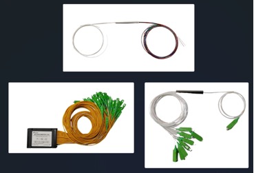
Depending on the application scenario, optical splitters can have different physical forms:
· mini splitters or fanout and bare PLC splitter (with or without optical connectors, very small dimensions for indoor or outdoor applications),
· small box-shaped splitters (optical splitters with connectors, plastic housing (ABS), for installation in various indoor cabinets),
· 19-inch rack-mounted splitter units (optical splitter with connectors, for installation in a 19-inch cabinets in CO/HE/building),
· slotted splitter units/mini plug-in type PLC splitter (optical splitter with connectors, metal housing, for various indoor or outdoor cabinets),
· tray splitter units (optical splitters with connectors, for installation in 19-inch cabinets in CO/HE/building),
· indoor wall-mounted splitter units (optical splitters with or without connectors, for installation of various indoor optical distribution boxes ) and
· outdoor splitter units (optical splitters with or without connectors, for the installation of various outdoor optical distribution boxes).
According to the number of inputs, there are two types of optical splitters commonly used in PONs:
· 1:N (one input and N outputs)
· 2:N (dual inputs and N outputs)
In general, optical splitters with one input are most often used. Optical splitters with two inputs enable a test point and construction of downstream protection (types B and C).
One of the most important divisions, they can be divided into two large groups:
· Asymmetrical (unbalanced) optical splitters or taps. They are the most common 90/10, 80/20, 70/30, and 60/40. They are used to tap fiber optic systems for monitoring or to build FTTx PON networks in rural areas.
· Symmetrical or balanced optical splitters. Here the input signal is divided equally among all outputs. They are most often used in FTTH PON networks, such as 1:2, 1:4, 1:8, 1:16, 1:32 and 1:64.
Attenuation of a Splitter
The ideal attenuation of a symmetrical optical splitter is calculated according to the following formula:
Asplitter (dB) = 10*log10(1/N),
where N is the number of divisions of the optical fiber.
In practical use, the splitter will have higher loss due to the inefficiency of the splitter due to its imperfect manufacture.
We can see the attenuation of typical symmetrical splitters in the table below.
|
Parameter |
Specification |
||||||
|
Wavelength (nm) |
1260 – 1650 |
||||||
|
Type |
1:N |
1:2 |
1:4 |
1:8 |
1:16 |
1:32 |
1:64 |
|
Ideal loss (dB) |
|
3 |
6 |
9 |
12 |
15 |
18 |
|
IL (dB) |
Typical |
3.6 |
6.8 |
10.0 |
13.0 |
16.0 |
19.5 |
|
(P/S) Max |
3.8/4.0 |
7.1/7.3 |
10.2/10.5 |
13.5/13.7 |
16.5/16.8 |
20.5/21.0 |
|
Optical splitters can be built with or without optical connectors. Bare fibers are supplied for splicing couplers into the cable plant. SC, LC, and E2000 with UPC (PC) and APC ferrules are most often used as optical connectors. There are variants for indoor and outdoor applications. Outdoor applications require additional protection of optical connectors (typically IP68).
Optical splitter in FTTx and POL
During the design of a PON FTTx and POL networks, it is very important to determine the splitting of optical fibers, the number of splitting levels, and the location of the optical splitter.
Splitting of Optical Fibers
The splitting of optical fiber depends on the PON standard (e.g. GPON - max 128, typical 32 or 64, and XG(S)-PON - max 256, typical 64 or 128), the maximum distance between OLT and ONUs (typical distance is up to 20 km, but max theoretical distance can be 60 km (GPON) or 100 km (XG(S)-PON)), the bandwidth, and the FTTx scenarios.
The Number of Splitting Levels
Optical fiber can be split into one or more splitting levels. The recommended number of splitting levels is one (centralized solution) or two (cascade solution).
If the number of splitting levels is greater than 2, it can be a problem during network maintenance and troubleshooting. The main problem is the OTDR measurement. There are situations in FTTH and POL networks when confusion can occur if the optical splitters are at a short distance from each other (e.g. 2 or 3 optical splitters are located in the same optical distribution box). OTDR can show this as a single event or we cannot see events between optical splitters (e.g. bad splice between optical splitters).
Location of Optical Splitters
The optical splitter can be centralized - only one optical splitter on the OLT PON port which means every user had their own fiber direct to the head end. The optical splitter is located in the Headend (HE), Central Office (CO), Computer Room (Main Equipment Room) or in building. The centralized solution has two segments of ODN - feeder and drop segment.
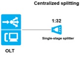
This solution is a typical solution in environments with high subscriber density (PON FTTx) and where there are a large number of rooms/offices (POL). The optical splitter is a symmetrical splitter with optical connectors (typically SC/APC or SC/PC), most often located in patch panels or special indoor cabinets. This solution requires optical cables with a large number of optical fibers, it is very simple to implement, maintain and troubleshooting.
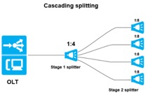
Cascade connection of optical splitters is used in suburban and rural areas (PON FTTx) and where there are a large number of floors and rooms/offices (POL). The first optical splitter can be a symmetrical splitter or tap, the second and third optical splitter is a symmetrical splitter. The cascade solution has feeder, distribution and drop segments of ODN.
In these solutions, optical splitters are installed in special plastic/metal indoor or outdoor boxes/cabinets/closures. Optical splitters can be with or without optical connectors. The last optical splitter on the network is most often with optical connectors (typically SC/APC or SC/PC). This solution is more complex for implementation, maintenance and troubleshooting, but high-capacity optical cables are not required.
Testing of optical splitters
Optical splitters should be tested before installation, after installation, and in case of problems.
The double-ended method is used to test the splitter before installation. This method uses a test source (TS) with a reference cable and an optical power meter (OPM) with a reference cable. After the calibration is done at 0 dB, the measurement is started. Because it is a bidirectional element, the optical splitter is tested at both ends, using working wavelengths, e.g. for GPON FTTH 1490 nm and 1550 nm for downstream and 1310 nm for upstream. OLTS (Optical Loss Test Set) can also be used for this testing. If it is a 2:N splitter, it is necessary to test all outputs and both inputs.
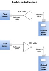
Insertion loss testing of splitters is done in both directions.
After the optical splitter is installed on the network, measurement is also required. OTDR instruments are used for this purpose.
All PON FTTx and POL networks have one or more optical splitters. The existence of an optical splitter in the network introduces confusion during OTDR testing. Optical splitters introduce a large attenuation, a 1:2 splitter introduces as much attenuation as an optical fiber about 10 km long (>3dB). The existence of an optical splitter on the display of OTDR shows as a large drop.
If we take the example of a FTTx or POL network, where there is only one optical splitter, e.g. 1:8. When measuring downstream, after a large signal drop caused by the splitter, there is confusion caused by the combination of the of multiple traces of each downstream fiber, creating an unusual trace can be seen on the OTDR display. This makes it difficult to find problems on the trace. Upstream measurement, using standard OTDR instruments, requires disconnection of the OLT PON port in the CO/HE (OLT) and testing from the location of each user. OTDR measurements show the trace from the subscriber to the CO/HE (OLT), where a large drop is observed due to the existence of the optical splitter.
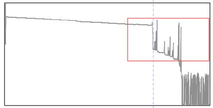
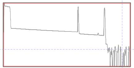
OTDR traces of FTTH PONs, downstream (L) and upstream (R)
Nowadays, some OTDRs use filtered wavelengths of 1625 or 1650 nm. These instruments do not require the PON port to be turned off, which is very important to keep the service constant. In addition to these OTDRs, today there are numerous specialized instruments and software (e.g. VIAVI and EXFO instruments and software) that recognize the existence of an optical splitter and can recognize the complete trace (determining the attenuation and the location of events such as splitters, connector pairs, fusion slices, etc.).
Vladimir
Grozdanovic is a graduate electrical engineer for telecommunications with more
than 10 years of experience in access networks (HFC and FTTH) in large cable
operators in Serbia (SBB and Jotel).
For more information on FTTH PON architecture using splitters see the FOA Guide:
Testing
splitters, couplers and other passive devices