
Bad Examples
of Aerial Construction In FTTH Networks In Eastern Europe
Vladimir
GrozdanovicAn aerial FTTH network is the most common way of FTTH network deployment. Generally, aerial FTTH networks are built in rural and sub-rural areas. However, in many countries around the world, aerial optical networks are also present in urban areas, especially in developing countries, because aerial FTTH networks present a simple and inexpensive solution. This article will examine the problems of poor installation practices of FTTH networks in the emerging economies.
There are many causes that lead to the poor installation of FTTH networks. Many telecommunication operators want to cut the costs and use low-quality, incomplete or inadequate equipment, as well as untrained staff. Insufficient or improper planning of optical networks is an additional problem. The operator installs an optical cable with insufficient number of optical fibers, so later, a new cable has to be installed. The consequences are visible across the network on every pole in town.
Furthermore, many cities have multiple telecommunication operators, and each operator uses their own optical cables. There is no single optical infrastructure. Frequently, operators use two or more cables and there are differences in equipment, such as optical closures and optical distribution boxes on the same pole, as shown in Figure 1.
The issue of improper installation of FTTH networks can lead to serious negative effects. The sheer amount of equipment present on a pole leads to more complicated technicians’ workload. It may also pose safety concerns for the those working on site. Another consequence of this practice is an overall unappealing urban landscape. The examples that follow will illustrate these points.
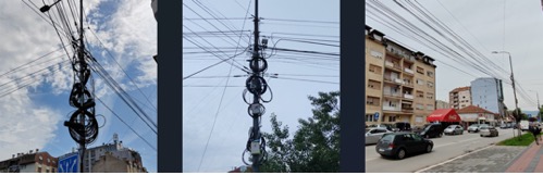
Figure 1 – Multiple cables and different equipment
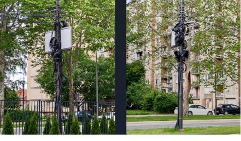
Figure 2 - a hybrid of an underground and aerial FTTH installation can be seen with each pole holding six optical closures and one optical distribution box.
The installation of wooden poles must meet all technical requirements and standards, especially the depth of the hole. Primarily, this could be a dangerous working environment not only for technicians, but also for pedestrians and traffic. If standards are not met, poles often fall, as we can see in Figure 3.
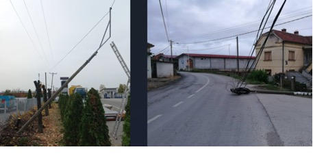
Figure 3 – Fallen poles
There are instances when metal poles are deformed due to the pull of the cables. Additional metal elements are often placed on small metal poles to ensure a safe cable height (image on the left). As a result, the cables pull the poles which cause the poles to bend, as we can see in Figure 4.
Figure 4 – Bent metal poles
We also have examples where foliage took over the poles. In Figure 5, we can see a large number of different copper and optical cables covered by a plant. Working on such poles can be hazardous.
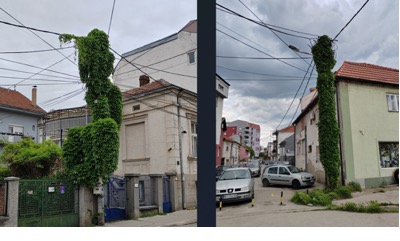
Figure 5 – Native plants taking over
Next, there are situations where a cable is fixed on a pole without a steel pipe ring. Instead, Figure 6 shows that a steel wire is used to connect the cable to the pole. The second example uses electrical tape for the same purpose. Over time, the cable on the pole might fall and could be damaged as a result.
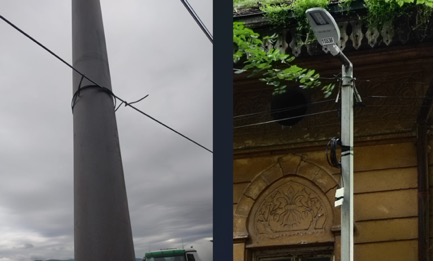
Figure 6 - Fixed cables on poles without steel pipe rings
Another example of improper cable installation pertains to the height standards. There are situations where cables are not at the prescribed height. This can quickly lead to cable breakage or damage. In Figure 7 below, this situation is evident.
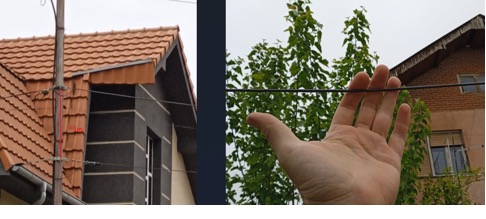
Figure 7 – Low cable installation
Further to the point, many telecommunication operators do not use cable slack holders. Steel wires and/or electrical tape are used for spare cable length, optical closures and optical distribution boxes. It often happens that cables and equipment fall off or hang low. Consequently, they could easily be damaged (see Figure 8).
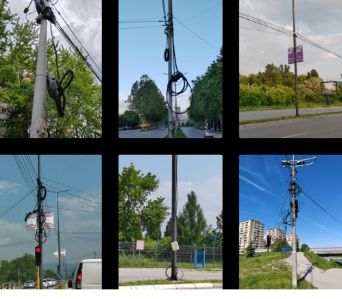
Figure 8 – Low-hanging or fallen spare
Next, during the construction of the optical network, a spare optical cable is left at certain points in case of an accident. The coiling of the spare is often done poorly. This can lead to fiber attenuation and damage to PVC tubes and optical fibers. Figure 9 shows a cable that has been compressed as it was coiled and fixed.
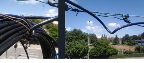
Figure 9 – Compressed (kinked) cable
Working with optical closures requires trained stuff. If heat shrinkable tubing is not used in the right way, it can allow water and moisture to enter the optical closure, as we can see in the figures below. Ingress of water and moisture leads to attenuation of optical fibers, and can damage them.
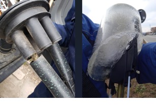
Figure 10 – Unsealed optical closure leading to ice forming (sometimes called a "splicecicle" - like Popsicle!)
Another frequent problem with optical closures stems from working with splice cassettes - splicing and installing optical fibers. Precision and a pedantic approach is required. Examples of inadequate installation of PVC tubes and fibers can be seen in Figure 11.
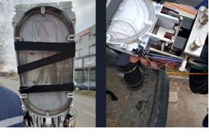
Figure 11 - Inadequate installation of PVC tubes and fibers
Then, different methods are frequently used to connect buildings and houses. Many of them do not meet technical requirements and are done poorly and unprofessionally. In the figure below, we can see that the pole is inappropriately connected to buildings and houses. The pole is missing a steel pipe ring and a ZnFe (galvanized) tape is used instead. To complete the workload quicker, additional ZnFe metal tape and angular clamps are used to connect the buildings.
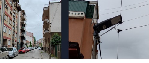
Figure 12 - ZnFe (galvanized) metal tape and angular clamps used to establish connection
In the next figure, we see how three elements are fixed to the house. However, only the first element is used to attach the drop cable.
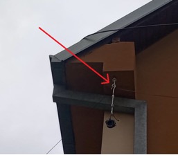
Figure 13 – Unnecessary use of equipment to establish a connection
Subscriber connection is done from the optical distribution box in which the optical splitter is located. However, the next two figures are an example of a subscriber connection using ATB – Access Terminal Box (on the left) or optical cassettes (on the right). In the figure on the left, we can see two ATBs, one of which is in a plastic bag. Additionally, electrical tape is often used for this purpose. These methods are inappropriately used frequently when troubleshooting broken drop cables.
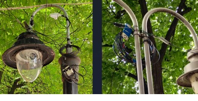
Figure 14 – Inappropriate use of ATBs (Access Terminal Boxes) and splice cassettes
A poor example of connecting drop cables is the use of jacket of coaxial cables (usually RG6), as illustrated in the next figure. This type of connection is also very commonly misused in indoor applications.
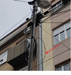
Figure 15 - A poor example of connecting drop cables.
Poles of public lighting or electrical distribution are displaced for reasons, such as changed technical requirements, aesthetics, or sustained damage. Here are examples of what happens with the equipment of telecommunications operators when poles are removed. In the first image in Figure 16, the equipment was left hanging. In the other three images, the pole has been removed but the new pole has not been installed. Cables and equipment (optical distribution box, angular clamp and tension clamps) are tied to the roadside sign and the bridge. Due to the traffic, in the third image, we can see that the cables are resting on ladders, which are fixed to a bridge.
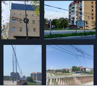
Figure 16 – Examples of the state of telecommunication equipment once public lighting poles are moved.
In the next example, an optical distribution box is fully utilized, and a new one is installed not in line with technical standards. The X-shaped black electrical tape is used faultily to indicate that the first box is used up.
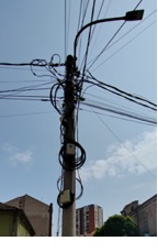
Figure 17 – Inappropriate installation and marking
Finally, plastic bags or tree branches may become entangled in optical cables over time. These are retained due to the large number of cables. There were situations where cables became tangled. We see such examples in the following figures.
Figure 18 - Plastic bags and tree branches caught up in cables
Vladimir Grozdanovic is a graduate electrical engineer for telecommunications with more than 10 years of experience in access networks (HFC and FTTH) in large cable operators in Serbia (SBB and Jotel).
FOA Guide Table of Contents
(C)2023, The Fiber Optic Association, Inc.