
What Is A Data Center?
Data centers are facilities that store and distribute the data on the Internet. With an estimated 100 billion plus web pages on over 100 million websites, data centers contain a lot of data. With almost two billion users accessing all these websites, including a growing amount of high bandwidth video, its easy to understand but hard to comprehend how much data is being uploaded and downloaded every second on the Internet. A data center, as defined in TIA-942, Telecommunications Infrastructure Standard for Data Centers, is a building or portion of a building whose primary function is to house a computer room and its support areas. That definition seems quaint in the era of giant warehouse-sized data centers with hundreds of thousands of servers, switches and storage and up to a million interconnections. The main functions of a data center are to centralize and consolidate information technology (IT) resources, house network operations, facilitate e-business and to provide uninterrupted service to mission-critical data processing operations. Yes, it is what we used to call the computer room before it grew to fill giant buildings! Data centers can be part of an enterprise network, a commercial venture that offers to host services for others or a co-location facility where users can place their own equipment and connect to the service providers over the buildings connections. Data centers can be big like a Google, Facebook, Amazon or Apple data center. Probably nobody has data centers bigger than Google. (OK, maybe NSA.) Google has has some very artistic photos taken of their data centers and put them online so all can see them. You can learn more about Googles data centers here: http://www.google.com/about/datacenters/inside/ Or small like what we used to call the computer room - this one at the new San Diego public library. It's just big enough to store some basic library data and be the nerve center for their passive optical LAN (POL.) 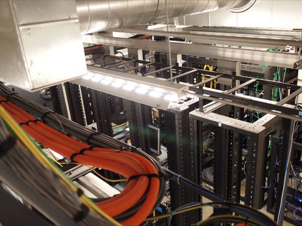 Data centers are filled with tall racks of electronics surrounded by cable racks. And power cables. And cooling equipment. Data is typically stored on big, fast hard drives although there is some movement to solid state drives. Servers are computers that take requests and move the data using fast switches to access the right hard drives. Routers connect the servers to the Internet. Speed is of the essence. Servers are very fast computers optimized for finding and moving data. Likewise, the hard drives, switches and routers are chosen for speed. Interconnection use the fastest methods possible. Faster speed means lower latency, the time it takes to find and send the data along to the requester. While speed is a primary concern for data centers, so is reliability. Data centers must be available 24/7 since all those 2 billion Internet users are spread all around the world. Reliability comes from designing devices with redundancy, backups for storage, uninterruptible power and fighting the #1 enemy of reliability, heat. Heat is generated by all the electronics, and the faster they run, the more power they consume and the more heat they produce. Getting rid of heat requires lots of air conditioning which can consume as much power as the data center electronics itself. Uninterruptible power requires generators, batteries or even fuel cells and those generate heat from inefficiency also. Data centers consume vast amounts of power. A few years ago, the magnitude of this consumption became apparent in surveys of giant data centers. Estimates are that data centers consume more than 3% of all the power consumed in the US, which hosts the majority of data centers, an amount more than consumed in total by almost half the states! Power consumption in a data center is more than 100 times as much per square foot as the average commercial property. Within the data center, the focus is on moving data, reducing power and heat and ensuring reliability. Thats done by choosing components and systems, designing facilities and installing them properly. Data Center Architecture The data center serves the LAN and WAN. The data center is comprised of switches connecting the users to servers and more switches [S} connecting servers [C] to storage [D]. This is probably a good point to say that data centers follow typical high tech linguistics it has its own language and many TLAs (TLA = three letter acronym) sometimes different from vendor to vendor. We will try to avoid this language issue by using plain English. 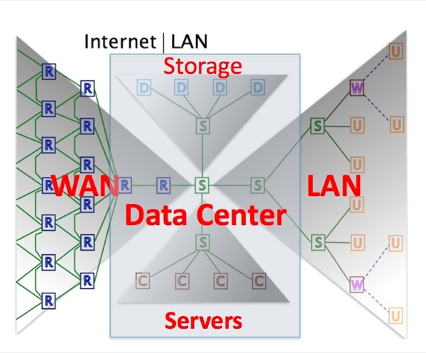 Data center architectures often include redundancy and multiple connections between servers, storage and switches. Thats whats generally called a mesh network because when you draw in all the connections it looks like a mesh. That also means data centers can have very large numbers of cables to make all these connections. Co-Location Data Centers Some data centers are co-location centers where customers can place their equipment in a warehouse type location which provides power, AC and service provider access (as well as high levels of security. Customer equipment is generally in a "cage" - literally, a wire cage structure - and may connect to carriers at an entrance facility cage and other co-location customers in what is generally called a "meet me" cage that allows connections without going outside the facility on service provider links. 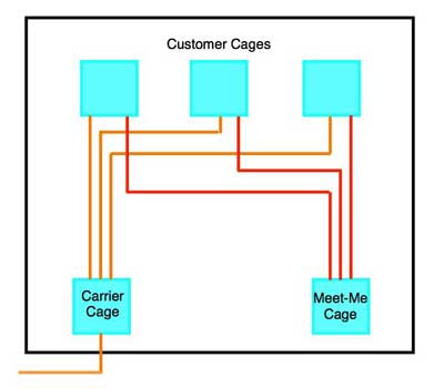
Data Center Switch Architecture Because of the number of servers typical in a data center, a tiered architecture of switches are used. Access switches connect groups of servers and interconnection switches connect the access switches. Some architectures have added a third level of switches but since that adds complexity, cost and latency pus used more power and creates more heat, a more streamlined architecture is being used by many data centers. 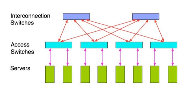 Like most tech areas, different vendors or groups have different names for some of these components. This switch architecture is sometimes called fat-tree or Spine-leaf. Interconnection switches (also called aggregation switches) may also be called core switches and access switches may also be called edge switches. Earlier designs used another (higher) layer of switches (core switches) that users realized were not necessary, practically doubled the cost and added heat and latency. Servers may have direct storage connections on Ethernet, Fibre channel (yes, its spelled fibre) or FCOE Fibre Channel over Ethernet or servers may connect to SAN switches which then connect to storage. Server connections to the storage area network (SAN) switches may be direct or through the access and or interconnection switches. Of all these connections, generally only the server-access switch connections may be on copper up to 10G. Below we have expanded the network architecture to include the routers connecting the data center to the LAN and WAN (outside world). 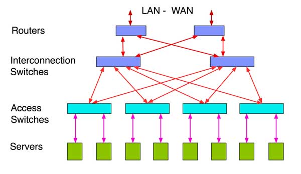 Then we have expanded the network architecture to include the storage are network (SAN) connecting storage to servers. When you consider the number of units connected and the multiple connections often used for redundancy to ensure reliability, you can see the amount of cabling that a data center can include. Mesh switching links allow servers to more easily use virtualization where one switch can provide services to more storage with lower cost and power usage. 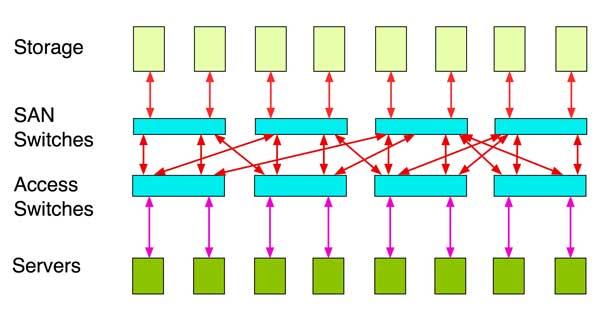 Standards For Data Centers Architecture And Hardware Until recently, data center architecture was specified by vendors who provided the hardware - switches and servers. With the advent of the mega- and hyper-scale data center, big users began to look for more efficient (and economic) ways to design and build data centers. This led to in-depth analyses of the way data centers were being built and how standards are being developed, specifically the move to singlemode fiber to allow equipment upgrades without cabling changes and "open-sourcing" the design of electronics. Open Compute Project - OCP is a user group started by Facebook because traditional vendors were not delivering the solutions needed. Traditional server/switch vendors were not delivering products with the performance/price needs of users in mind. Standards for data center cabling were not based on the realities of the business. In this case, the "realities" of the business was that technology was requiring upgrades to the data center every 18-24 months, way too fast for traditional switch/server manufacturer product upgrades and the typical 5-year cycle of standards development. Plus hyper-scale data centers had as many as 100,000 to 1 million connections, demanding the most cost-effective solutions. OCP, driven by Facebook, started by developing their own switches and servers and building the products themselves. Then they put the designs online - open source - and told everybody to try to make them better and/or cheaper. Before long, all the owners of large-scale data centers became members of OCP. Then they knew it was necessary to use singlemode cabling to be able to upgrade electronics without replacing cabling, so they worked with transceiver vendors for specific data center products that cost substantially less than transceivers for typical telecom use. That this model can work for OCP has shown that it is a valid model for developing standards - in fact it may prove to be a better method. When products reach commodity status - like data center servers and switches and their fiber optic transceivers - the input of real customers - not just manufacturers - is absolutely necessary to get the product designed right. And regular standards and product development cycles are way too long to be useful. Following the success of OCP, LinkedIn started Open 19 to cover lower cost equipment for smaller data centers. Reliability Reliability is a primary concern for data centers as downtime can be very painful to everyone. What defines reliability? UL's web page on their Data Center Certification Program states "The UL Data Center Certification Program will address the continued reliability of key components of critical data center infrastructure by integrating the multiple disciplines of electrical, mechanical, security, life safety, building automation, and telecom to create a comprehensive service." This is similar to the Uptime Institute's Tier Certifications or the European Standard EN 50600 by CIS. Cabling Data Center cabling is covered by TIA-568 and ISO-11801 through several standards, ISO 24764, CENELEC EN 50173-5 and TIA-942. These standards cover similar topics and offer lots of options for cabling in data centers. They also include more TLAs (three letter acronyms) than most standards. Many find the idea of standards like those covering structured cabling irrelevant for data center technology. It is difficult to be relevant in a technology than upgrades entire facilities - often including architectures - every 18-24 months when standards have 5-10 year update cycles. Perhaps they make sense for a small corporate data center/computer equipment room but probably not larger data centers. TIA started ~2006/7 to create a standard for data centers. Perhaps as a consequence of the length of development and review cycles for TIA standards, perhaps because it was created by vendors trying to apply TIA-568 structured cabling philosophy to data centers, it appears to be out of touch with current data center design. Unlike an enterprise LAN where once can conceivably create a cabling system that is applicable to many types of users (LANs, video, telephones, building security and management, etc.) data centers are highly specialized and designed for efficiency, hard to reconcile with a standardized cabling architecture.  TIA-942 Structured cabling is, by its philosophy, universal and that means it makes compromises in efficiency to allow more application flexibility. Data centers are so focused on efficiency that such an approach for cabling is often not acceptable - see OCP or Open 19 above. There are also issues with the points of view continuing to think that UTP copper cable is the primary cabling, including legacy systems like T-1 (1.5Mb/s) in the access provider connection options, and even looking to having several interconnects for parallel MPO-connector optics where the networks require such low loss budgets that multiple MPO connections will cause cabling to exceed the allowable power budgets. Data Center Cabling Designs Modern data centers have adopted unique cabling architectures that are appropriate for data center equipment usage. We will look at the two most common designs, top-of-rack and end-of-row. Top Of Rack 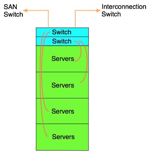 You will often hear about top of rack designs. In this design, the servers are in a rack with the switches that serve them. This makes the connection between the two very short so less expensive copper cables can be used within the rack either UTP or CX-4, as well as fiber. This actually limits the copper to each rack as other connections are made on fiber. If the rack connections are limited to 10G, this will save money. And there are options for low power 10G for short links on copper (CX-4 and proprietary UPT implementations) that save lots of power. The downside of this design is there are usually more switches to manage (i.e. keeping track of software upgrades). But the upside it the ease in cabling installation and management. End of Row 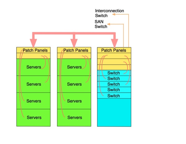 Whats called End-of-Row design comes from the idea that a rack of switches is on the end of a row serving the servers in that row and connecting to other racks of switches in other parts of the data center. The Server racks and switch racks are connected by UTP for up to 10G or fiber for any speed. The switch racks connect to Interconnection and SAN switches generally over fiber optics. End-of-Row racks of switches can be placed in the middle of a row or even be used to connect several rows of servers, depending on the density of equipment. Redundancy is often included, even having two EoR racks serving the same servers. Racks will generally have patch panels that allow equipment in the racks to connect over short patchcords to the large bundles of cables between the racks. Care must be taken to keep the patchcords of reasonable length otherwise the front of the rack is likely to become an unmanageable mess. Some designers seem to think that EoR is more efficient from the switch standpoint (more port utilization) and easier to manage. The downside is the architecture is less flexibility, the need to manage large bundles of UTP cables, more cabling infrastructure, and lack of upgrading capability beyond 10G until (unless?) Cat 8 becomes real. Making Connections Data centers can have lots of connections. Sometimes they grow organically and the back side of the racks begin to look like this. Good luck troubleshooting this system! 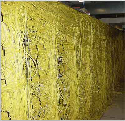 Data centers generally use Ethernet, although Fibre Channel (yes, its spelled fibre) has been used for storage area networks (SANs). However the trend is to now carry Fibre Channel over Ethernet to simplify the overall data center networks. Lots of choices are available for data center media classic UTP cable, coax, multimode or singlemode fiber and hybrid active optical cables (AOCs) that are fiber cables with permanently attached transceivers. Data Center Cabling Options
Here is a quick summary of data center cabling options. Coax and AOCs are used for short (!<5m) links, UTP can be used to its usual 90+10m limit, MM fiber can work over a range of 450 down to 100m depending on the type of fiber chosen but is very limited on power budget, meaning the cable plant must be low loss. SM fiber is becoming more popular because it offers the usual fiber advantages basically unlimited bandwidth and distance. The cost issue always comes up in discussions of media choice. UTP is usually cheaper but UTP transceivers consume ~5x as much power as fiber and that costs twice because it will cost for electrical power and then an equal amount to cool the excess heat it generates. MM fiber uses cheaper transceivers but much more cost in the cable plant when parallel optics are used for 40 or 100G. Long term, SM may be considerably cheaper and uses much less space in crowded data centers. 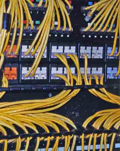 Cat 6A UTP works with 10G Ethernet, Cat 5E with 1G Ethernet. Its relatively cheap but consumes `5x as much power as a fiber link. It will also require much more space in the cable trays or under the floor probably too bulky for under the floor often and for Cat 6A at 10G you have to worry about alien crosstalk from cable to cable. One big disadvantage of the copper is the power consumption of transceivers. Due to the digital processing needed to make a copper solution work, a copper transceiver may consume up to 5-6W of power almost ten times as much as a fiber transceiver that consumes only 0.5-1W. A new UTP standard for Category 8 cabling for short (<30m) links in data centers has been approved. Cat 8 is only intended for short links and will consume lots of power. Somebody will probably find a way to make UTP work at 100G too, but who knows how much power that will take. 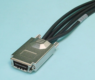 This is a CX-4 cable for 10G which uses four small coax cables. Good for short links - ~5m connections on a rack or rack to an adjoining rack. It requires a SFP module interface. 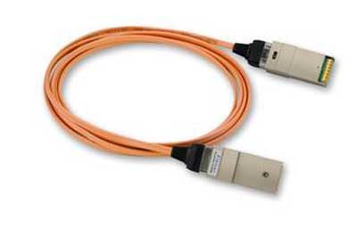 Active optical cables use mm parallel optics with a pluggable transceiver permanently attached to the cable. They are also used for short links, The transceivers plug into SFP receptacles. 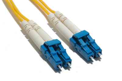 Multimode fiber has become widely used for up to 10G. VCSEL laser sources are cheap and multimode fiber easy to install. But MM is running out of bandwidth at 10G so parallel optics with separate 10G channels are used at 40G and 100G. 40G uses 4x10G channels and 100G uses 10x10G channels that has a major impact on the fiber count needed to support equipment. MM links at 10G are also power limited due to the bandwidth penalty caused by the limited modal bandwidth of the multimode fiber. MM links may only have ~<2dB loss budgets meaning that the data center cable cannot have many interconnections especially with the MPO multifiber array connectors which are inherently higher loss than single fiber ceramic-ferrule connectors like LCs and SCs. For example, if one uses the TIA specification for connector loss of <0.75dB/ connection (connector mated pair), one could only have two connections in a cable plant link, basically the two connections needed to go from the permanently installed cable plant to the patchcords connecting the equipment, e.g. no interconnections in the installed cable plant. A newer variation for MM fiber is short wavelength CWDM using 4 VCSELs at wavelengths in the range of 850-950nm on special fiber now designated OM5 or wideband MMF. This promises to allow duplex links over MMF. The issues with this method are availability of components, particularly transceivers, cost compared to SM fiber and of course the lifecycle cost when it comes time to move up to 200G, 400G or more. See details below. Simplex or duplex MM like SM fiber uses LC connectors because they are used in the transceivers for their smaller size. Parallel optics and prefab cable assemblies (more on those later) use the MPO connector which has 12 or 24 fibers per connector. The limitation of parallel optics with MPO connections includes the masses of fibers required and the fewer interconnects allowable because of the typically higher loss of the MPO connector. 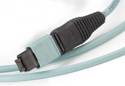 MPO connector - more on MPO connectors and testing them Here is an example of a 40G and 100G solutions on multimode fiber. 40G uses a 12 fiber MPO with 4 channels each at 10G for transmit and receive on separate fibers, so there are 4 transmit and 4 receive fibers. Since the MPO connector has 12 fibers, the center 4 are unused. 100G uses 10 channels each at 10G for transmit and receive on separate fibers on a 24 pin connector, so there are 10 transmit and 10 receive fibers. Since the MPO connector has 12 fibers in each row, the center 4 are unused. There is a version of 100G being developed that uses 4 X 25g channels which will have shorter reach. This design should use a connection scheme like 40G on a 12 fiber connector. MM transceivers use inexpensive 850nm VCSELs so the transceivers are cheaper than singlemode but the fiber optic cable plant uses many multimode fibers so the cable plant is more expensive. Singlemode fiber has practically unlimited bandwidth and distance capability when used in data centers. Unlike the parallel 10G channels used with MM fiber, singlemode uses wavelength division multiplexing WDM to transmit multiple channels over one fiber at different wavelengths. Thus 40G uses 4X10G wavelengths and 100G is achieved using 4x25G wavelengths. CWDM transceivers cost more than parallel MM transceivers at the current time, but the cabling cost is much lower and expected higher quantity usage will drive costs down. Look what 100million users did for the lasers and CWDM used in fiber to the home (FTTH.) Both MM and SM fiber use LC connectors. because they are used in the transceivers for their smaller size. SM designs may incorporate LC-APC connectors to reduce reflectance. Moving Faster Data over Cabling Every data center begins with fiber optic connections to the Internet, usually to several providers for redundancy. Entrance facilities must be provided for multiple cables connecting to the outside communications networks. Incoming cables will terminate in racks with connections to routers that in turn connect to the servers hosted in the data center. These connections will carry vast quantities of data over singlemode optical fibers at 10-100Gb/s. Within the data center, the goal is to move data as fast as possible with the lowest latency and that means using the fastest possible data communications links. Gigabit Ethernet is too slow. 10 gigabit Ethernet and Fibre Channel are commonly used today. Fibre Channel is moving to 16 Gb/s and Ethernet is headed for 40 Gb/s and 100 Gb/s. The big data center users want 40/100 Gb/s as fast as possible and are pushing network standards committees and manufacturers to produce useable products as soon as possible. At 10 Gb/s, standard data links use multimode or singlemode fiber optics, coax cables or Category 6A unshielded twisted pair links (see table above). Of the three, fiber is the most reliable and has the lowest power consumption, especially if the links are long, saving as much as 70% over UTP copper links. Up to about 10 meters (33 feet) 10GBASE-CX4 on coax can be used on very short links effectively. Cat 6A consumes lots of power to transmit 10 Gb/s on longer links and generates more heat. Many data centers use coax for short links and fiber for longer links, but Cat 6A continues to be developed for lower power and is becoming more widely used. The next step up from 10G is to 40G or 100G. Some users are thinking about using the UTP Cat 8 cable in a rack as part of a 40G upgrade. Some big users are skipping 40G and going right to 100G, generally on SM fiber. The 40/100 Gb/s MM standards call for multiple 10 Gb/s channels run over parallel multimode optical fiber cables, the new MM fibe rWDM (see below) or WDM on singlemode fiber. The MM links require 8 fibers for 40 Gb/s (two fibers transmitting in opposite directions for each 10 Gb/s link) and 20 fibers for 100 Gb/s. These links use the MTP multifiber connector in 12 and 24 fiber configurations, the same connector used on prefab systems today so there are some unused fibers. Singlemode generally uses LC connectors. The largest users of data centers have expressed a preference for WDM on SM fiber for reduced cabling bulk and cost. Here is a table of the options for faster speeds. There is a lot of activity to add new variations, e.g. 200G and 400G and up in the standards committees, so keeping up with the latest standards requires checking the appropriate standards groups.
Beyond 10G, the issue is cost as well as cabling bulk. MM fiber generally uses parallel optics with 10G channels to build higher speeds. Short wavelength WDM is still limited in availability or support. The VCSEL sources used for MM are cheaper but it requires many more fibers and that can offset the higher cost of SM WDM transceivers. SM at 100G is especially advanced, using 4x25G channels over each fiber, making it much less complex in the cable plant. Discussions with big data center owners and contractors indicate a preference for going to SM. Transceivers are more expensive but cabling is much cheaper and easier to install and manage. SM also allows more flexibility in distance and numbers of interconnections. MPO connectors used in parallel optics have higher loss and the loss budgets are low, as low as 2dB, limiting interconnections. And perhaps most importantly, SM fiber allows for upgrades in equipment speeds - into the terabits/second range - without replacing cabling.
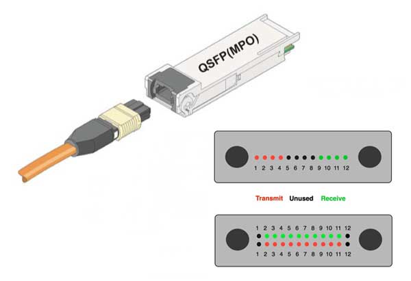 Multimode parallel optics uses lots of fibers in MPO array connectors. The 12 fiber MTP connector used on MM 40 and 100 Gb/s links and many prefab cable systems. 40G (4 x 10G) uses 4 fibers at 10Gb/s in each direction (top connector.) 100G (10 x 10G) uses either 10 fibers at 10Gb/s in each direction (bottom connector.) or for 100G (4 x 25G) 4 fibers at 25Gb/s in each direction (top connector.) Compare a 100G switch with 20 ports. Using MM fiber on a 10X10G link, you will have 20 MPO 24 fiber connectors and 480 fibers serving a single switch. *Think how many fibers you need for a rack! And about 15% of those fibers are wasted because the MPO connector has unused fibers, unless the connectors are only loaded for 8 or 10 fibers or you use one of the complicated MPO splitting schemes with modules that do the arranging of fibers.. At 40G (4 X10G) or 100G (4 X 25G), you lose 1/3 of all the fibers, but the 20 port switch needs only 240 fibers, half as many. With SM, each switch needs 40 fibers and 20 duplex LC connectors. SM has advantages on installation time, cabling cost, testing time and cost, probably enough to balance out the higher cost of transceivers and then think about the ease of upgrades. Even inside the servers, increasing speed and reducing power has led to the development of optical fiber interconnects. Intel is actively developing board level interconnects for their products, touting all the usual benefits of fiber. Future Options - MM Fiber WDM? Some new ideas are making MM fiber a possibility for up to 400G, or at least 100G on only two fibers. The idea developed by Cisco and Finisar is to use short wavelength WDM wavelength division multiplexing with VCSELs on an upgraded OM4 fiber, now standardized as OM5. The wavelengths uses are in the 840-940nm range with 30nm spacing. The fiber needs to be modified to have modal dispersion increased at longer wavelengths but benefits from the fact that the chromatic dispersion is reduced at longer wavelengths. Cisco is already using this technology and while it has been standardized it is not widely available commercially. 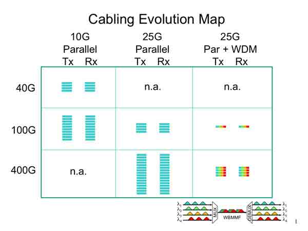 This graphic courtesy Commscope, OFS and Finisar shows how wide band MM fiber can be used for WDM up to 100G on 2 fibers and 400G on 8 fibers. Switch manufacturers are also proposing new 25G and 50G Ethernet options for server connections using MM fibers and advanced high-speed 850nm VCSELs. (Update 2020) With the work done by OCP to get 100G transceiver costs down almost 90% for data center applications, the movement to singlemode in data centers is nearing universal. 200G and even 400G transceivers are being tested already, showing the capability of singlemode fiber. Fiber Choices After making the choice of MM or SM, there are other choices to make, such as the fiber type. With MM, do you use OM3 fiber or the higher bandwidth but more costly OM4? Or maybe OM5 and hope that MM WDM products will be developed? Do you choose a prefab or field terminated installation. If field terminated, what kind of connectors (MPOs are not a good choice for field installation.) And if you have a choice, do you use regular or bend-insensitive (BI) fibers? Considering how cramped cables usually are in data centers, BI fiber is probably a good choice. (But remember that mixing BI MM fiber and regular MM fiber may incur excess losses when going from BI to regular fiber and that reference test cables must be of the same type fiber as the fibers being tested.) Likewise, SM offers similar choices. OS1 fiber is standard SM fiber cabled for premises use while OS2 is cabled for OSP use and lower loss because of the cable design. Both are low water peak fiber better for CWDM. And bend-insensitive (BI) fiber will perform better in cramped cable trays and racks. Cabling Design And Installation Most data centers will contain a mix of fiber, coax and UTP cabling. The connections to the Internet coming in from the outside world are going to be on singlemode fibers. Multimode fiber, either OM3 or the new OM4 high bandwidth fibers, are likely to be used for MM connections. Coax will be used on very short connections or Cat 6A may be used for short and medium length links. Another option for short links is active optical cables. Much of the choice depends on the data center design choices. Whichever media is used for interconnects, one thing is certain, there will be lots of cables! Cables from routers to servers, servers to other servers or switches and switches to storage devices. The volume of cables involved and the number of routes they can follow make planning the pathways and spaces carefully to prevent chaos in the data center. Cables may be run overhead or under floors. All cable trays must be properly sized for the expected cable loads. Under floor trays are generally wire mesh types while heavy-duty overhead racks are usually needed, especially when expected to carry large quantities of heavy copper cabling. Additional room should be provided for Cat 6A since cables cannot be neatly bundled to save space, because that may cause alien crosstalk between adjacent cables. 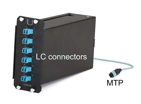 Prefab cable system with modular interface. More on prefab cabling. Because a Cat 6A or coax cable makes only one connection link per cable, multi-fiber optical fiber cables are big space savers. Prefabricated fiber optic cable systems using multi-fiber MTP style connectors not only save space but also installation time, since they just require installation and plugging together, no termination or splicing required. Fiber optic cables that are armored are sometimes used in the under floor trays to prevent cable damage when more cables are placed in the trays. 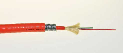 Armored indoor fiber optic cable If one chooses to install cable and terminate onsite, the installation is straightforward. Pull cables, set up a termination station and go to work. One can use either adhesive/polish or prepolished/splice connectors for single fiber MM but singlemode is best installed by fusion splicing on pigtails or using prepolished/splice connectors of the type used often for fiber to the home. APC connectors for singlemode connections might be a good idea as it reduces reflectance and problems it can cause. MPO connectors are generally supplied in prefab assemblies but can be terminated by fusion-splicing pigtails onto cables. Field termination in a data center can be a big project with so many connections, so some users look to prefab cable plants (preterminated cabling systems as some manufacturers call them). The good news is they are quick to install. Now for the bad news: The cable plant must be carefully designed so its not too long (requiring excess cable storage which may be hard to find in a crowded data center, nor too short with obvious bad consequences. Prefab cabling can be more costly than field termination. MPO connectors have higher loss than LCs or SCs when some links have very low loss budgets and can have higher reflectance which can adversely affect data transmission. These connectors are very sensitive to dirt and must be carefully cleaned, even on the connectors with alignment pins. Special microscopes are needed to inspect these connectors. Whenever one is installing prefab or preterminated cables, one must have protective covers over the connectors during installation to prevent damage. Damaged cables will probably be removed and replaced by a new cable which may take a few weeks to get delivered. If the system is prefab with LC modules as shown here, testing is straightforward, but as you will see, parallel optics with MPO connectors is more complicated to test. Cable Testing Cable testing is important for all cables. Cat 6A is highly stressed at 10 Gb/s so all terminations must be carefully made. Even fiber links, especially if they include multiple connections, must be tested since link loss at 10 Gb/s and above is quite small and intolerant of bad connections. MPO parallel optics present a particular problem for testing as there are few testers designed with MPO interfaces. MPO connectors used in parallel optics and prefab cabling systems and testing them. Various methods of testing parallel optics are covered in the FOA Guide section on testing. Cable Documentation Obviously cable plant documentation and labeling are critically important. In a facility that may have thousands of cables, its vitally important that each cable end and each port be logically marked to allow moving, tracing, testing and troubleshooting cables. Powering And Cooling The Data Center As noted above, data centers consume vast amounts of power and require large uninterruptible power supplies for reliability. All power requires conditioning for delicate electronic modules. Many data centers run dual power systems with dual power backup to ensure maximum reliability. This means dual UPS setups, dual generators and dual power distribution systems. 
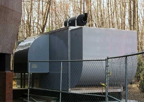 Battery backup and generator at a data center Power cables are usually under the floor on separate aisles from data cables. The actual layout of power and data cables has to be coordinated with the layout of equipment racks because cooling of the equipment has become quite sophisticated. Generally data centers are kept much cooler than regular offices to ensure proper cooling for all the equipment. Racks and electronics are designed for directional airflow to keep hot air away from other electronics and feeding cooling air to the racks. When you consider that the air conditioning will use as much power as the servers, careful design of air conditioning is very important. Cable racks must not impede cooling airflow. Because of the high power consumption, data centers have become a major focus of research on how to reduce power. Electronics manufacturers are developing lower power systems and using lower power fiber optic data links. Even the location of the data centers can affect the cost of power and design of a data center. The owners of big data centers like Google are well aware of the issues. In the Bay Area near their headquarters, Google uses solar photovoltaic systems to generate 30% of their power. Several major data centers are located on the Columbia River so it can utilize lower cost (and lower carbon) hydroelectric power. Cooling is a big problem in data centers. A single rack can use kW of power and most of it is converted to heat that must be removed. It may take as much power for cooling a data center as its equipment consumes. It's beyond the scope of this page to cover cooling issues but there is plenty of literature on the subject. Security Data centers are considered critical facilities and of course involve massive investment. Owners invest millions in preventing intrusion from the Internet from hackers and are also concerned with physically securing the facility. A typical data center will include state-of-the-art personnel entry systems, intrusion alarms and numerous surveillance cameras. This will often cover not only the actual building but the area in which it is located. Some data center owners even ban cell phones and WiFi from the facilities because of worries about data interference. Coordination is Key While data centers tap all the resources of the user, designer and the well-rounded contractor, it is important that the contractor be involved with the customer from the initial concept of the project. A successful data center will involve coordination among the customer, vendors, contractors and often even municipalities and utilities from the beginning of the project. Each party should contribute to the design to ensure that all issues like facility design, communications, power and security are covered properly. Table of Contents: The FOA Reference Guide To Fiber Optics |
|
|