
Outside Plant Construction GuideIntroduction Review Of Fiber Optic Technology. Project Preparation And Guidelines. Underground Cable Construction. Underground Cable Installation. Aerial Cable Installation. Completing Outside Cable Plant Installation. Aerial Cable InstallationAerial Cable Installation Deploying fiber above ground on poles or towers removes the need for underground digging and is particularly useful when the ground is uneven, rocky or both. Aerial installation is generally much less costly than underground construction also. Fiber in a duct solutions have a major aesthetic advantage; once installed, they are invisible, leaving no mark on the landscape. Unlike aerial installations, they are less affected by most adverse weather like high winds or freezing rain. But underground installations can be vulnerable to flooding damage. However, there are a number of reasons for choosing an aerial solution, such as:
Before beginning aerial installations, the design of the cable plant must be properly done and checked. Routes must be surveyed, ground conditions tested, all components procured and received. Permits from local authorities must be obtained and coordination with local agencies such as traffic and police must be properly planned. If poles exist already, it is required to have proper permits for adding communications cables and the poles must be made ready by the owner of the poles are authorized parties. This may take considerable time which must be factored in the planning of the project. Sometimes lightweight fiber cable may be lashed to previously installed cables such as older copper phone cables or CATV hardline coax, but proper permissions must be obtained. Prior to installation, the location of splice points and storage of slack cables must be determined and noted in the design. Splice locations should be chosen with the need for parking a splice truck, van or trainer nearby. Cable Jackets Polyethylene (PE) is the material of choice for use as an aerial OSP cable jacket. The performance of raw PE can degrade rapidly through exposure to sunlight but the addition of carbon black to the cable jacket absorbs the UV light to protect the plastic jacket of the cable. Jacket colors other than black are rarely used for aerial installations and then only for enhancing identification. 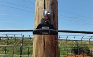 Safety Aerial cable installation can be hazardous as personnel may working at considerable height above the ground on ladders, bucket trucks or even climbing poles and near electrical transmission wires. All workers should have proper training and personal protective equipment before being allowed to work on aerial installations. Pole Handling Personal Protection Equipment (PPE)
Climbing Ladders
Transportation of Poles Poles must never exceed the 0.5m vehicle overhang and must have a red flag secured on the overhanging end. Poles that are loaded onto a pole carrier must be secured to ensure that the cargo does not move while it is in transit. Pole Off-Loading Procedure Ensure that the removal of any one pole will not cause shifting or rolling of any of the remaining poles. Step
1: Unfasten the poles.
A pole
must never be dropped on the ground, as this could damage
the pole and/or cause injury to team members.Step 2: Slide one pole at a time towards the rear end of the vehicle. Step 3: When the pole reaches its equilibrium point, the persons on the vehicle must raise their end slowly. Step 4: The persons on the ground slowly pull the pole until 1m of it is left on the back of the vehicle bed. Step 5: The persons on the ground receive the pole and gently place it on the ground. Pole Handling Ratios Smaller poles may be handled manually with sufficient personnel available but larger poles require proper mechanical aids. 7m
pole =4 people
8m pole =6 people 9m pole = 8 people or a mechanical aid 10m pole = mechanical aid. 11m + pole = mechanical aid Survey 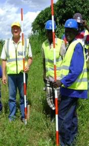
Survey Equipment and Tools
Survey - Gather Route Information
Pre-Install Meeting A pre-install meeting or meetings must be held to discuss the survey results, the optimum pulling sites, span lengths, installation equipment and hardware requirements, logistics, splice locations, terrain and other vital installation topics. Checks to be undertaken prior to commencing with the planned aerial work
Wooden pole inspection (prior to installation)
Hole-digging Tools  The tools provided for hole-digging include picks, shovels, earth augers, crowbars, drills and sledge hammers. The tools to be used for any particular work are determined predominantly by soil conditions. On large projects and wherever ground conditions permit, hydraulically powered Earth Augers can be used. It looks much like a corkscrew and produces extremely clean holes. Pole Holes Poles must be buried sufficiently deep for stability. The depth depends on the height of the pole. Check with local authorities to confirm these dimensions. 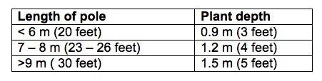 All excavations for pole holes will be such that the survey peg indicates the center of the hole. If the holes are too large, the soil will be unnecessarily disturbed and the poles will not be supported by solid earth. (A diameter of approximately 400mm (16 inches) is recommended). Where a hole is dug on sloping ground, the depth of the hole shall be measured from the lowest point on the ground surface. In extreme rocky conditions where holes cannot be excavated to the specified depth, an arrangement between contractor and client can be reached for poles to be set in concrete. Poles set in Concrete 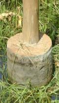 Where poles are planted in soil that is difficult to compact, such as sand and swampy areas and in extreme rocky conditions, the poles can be cast in concrete. Only new wooden poles can be set in concrete. The hole must be circular in shape. The hole diameter must be kept to a minimum, but be sufficiently wide to accommodate at least 85mm of concrete between the sides of the pole and the undisturbed ground. The concrete to be used must be made from a mixture of 1 part cement, three parts sand and three parts crushed stone (1:3:3 mix - 15MPa). Concrete must not be compacted around the poles, but thoroughly tamped around the pole with a suitable wooden stick, until the hole is filled. The bottom of the pole must be allowed to breathe therefore, backfill with 10cm of soil before pouring concrete. Pole Spacing It is advisable to maintain a uniform span length and depart from this only when it is rendered necessary by conditions such as: (1) uneven ground (2) sharp bends (3) or to avoid dangerous positions. This may necessitate the planting of additional poles or omitting of poles. Steel measuring wires for standard span lengths should be made up locally. When the length of span has been chosen the appropriate wire should be used to determine the distance between successive poles. A steel tape measure should be used for checking the length of the measuring wire daily during the survey. Local ADSS Span Lengths All dielectric self-supporting fiber optic cable can be installed without a messenger over relatively long spans. ADSS installation will be covered later. 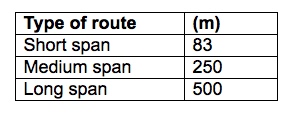 Pole Planting Process
Suggested Pole Planting Work Practices
Types of Stays Terminal Stays Terminal stays are provided where the route starts and ends. This stay must be on the side of the pole opposite to the direction of the cable route. 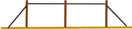 Line Stays Line stays should be installed at every 13th pole along the route or spaced alternatively as per specification. Line stays must be installed on poles either side of rivers and road crossings where normal span lengths are exceeded. 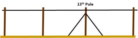 Wind stays & Angle stays Wind stays are used to stabilize a cable route against wind. Fitted at 90˚ against the direction of the cable route and on either side of a pole. Angle stays are used to counter-act a change in direction of the cable route by more than 15˚or as per client specs. 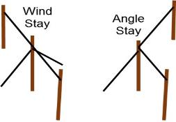 Stay Guards 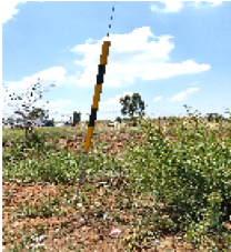 Stay guards must be fitted on all stays exposed to pedestrians, cyclists or vehicles, to make them more visible. Struts 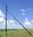 Struts can be used as an alternative to where stays create traffic hazards, block roads or where a property owner objects to the fitting of a stay. Struts must be installed on the opposite side of the pole to where the angle stay would have been fitted, to counteract cable strain. Stay Holes The cross-section of the hole shall be confined to the smallest size necessary to accommodate a stay plate. 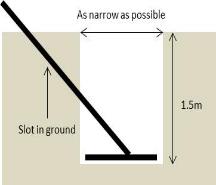 The depth of stay holes shall be 1.5 ( 5 feet) meters or at such a depth where the unthreaded portion of the stay rod protrudes by no more than 25mm ( 1 in) above ground level. Stay rods without plates may be used where solid rock is encountered. The stay rod is now inserted in a hole drilled into the rock and secured with cement. In difficult to dig ground conditions shallower holes are allowed subject to approval and shall then be backfilled using concrete. Spread/Height Ratio The spread is the distance from the foot of the pole to the point to where the stay enters the ground. 
Termination of Stay Wire to Pole or Crosshead 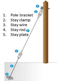
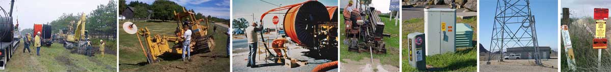
Messenger Wires (Suspension Strands) If the cable is to be lashed to a messenger wire, the messenger wire must be sufficiently strong to support the cable under expected environmental conditions, including wind and possible ice in winter. If designing an aerial system requires installing a messenger wire, the design must include calculations for the messenger wire size based on expected cabling loads, span lengths and other possible uses including future cables being added to the span on the same messenger wire. Designs for the messenger wire should include the type of wire chosen, how it is attached to the poles for both dead ends and crossovers, slack and sag, etc. The proper design is the minimum acceptable size of messenger wire with adequate strength, because larger wires weigh more and are more susceptible to wind and icing. Consulting with a knowledgeable applications engineer, often those with the fiber optic cable supplier, can provide the knowledge needed to design and install the proper messenger wires. 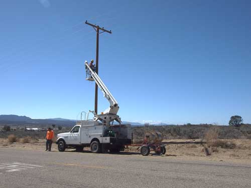 Installing messenger wires on electrical utility poles for fiber installation. Lashing Fiber Optic Cable To A Messenger Cable The installation process of a lashed aerial fiber optic cable will generally require one or more bucket trucks to allow workers to reach the location of the lashing, guide cables around poles and through trees or other obstacles and move the lasher across poles. 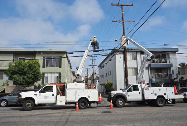 Two trucks lashing cable to a messenger. The lasher is just to the left of the pole. There are two ways to lash cable to a messenger, the moving reel method and the stationary reel method. In the moving reel method, the reel is moved slowly under the route while the lasher is pulled along to lash the cable to the messenger. This method generally only works when the reel vehicle can drive along the entire route. 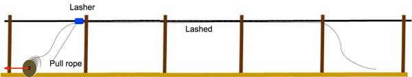 Moving reel method The stationary reel method leaves the reel in place and the cable is pulled along the route and temporarily attached to the messenger with cable blocks. After the cable is placed, the lasher is pulled along the route to lash the cable. The lasher can push the blocks to the next pole for removal or be removed as the lasher moved along the route. 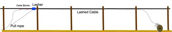 Stationary reel method 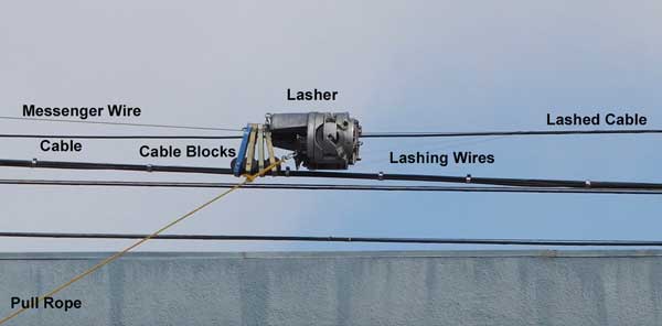 Lasher being pulled for stationary reel method Extra Fiber For Handling And Service Loops At the ends of every section of cable where it is being spliced or terminated, the cable must be long enough to reach the splicing van or trailer plus about 5 m (16 feet) to allow for entry into the splicing van or trailer and have sufficient cable length for preparation and splicing. The cable plant design should include plans for location and placement of service loops to safely and neatly store this excess cable and a splice closure after splicing is complete. Installation Of All-Dielectric Self-Supporting (ADSS) Cable ADSS is a special OSP cable that is designed to sustain larger tension loads over long periods of time. ADSS cable does not need any additional support so it is small, lightweight and easy to install. Because it is non-conductive, it can be installed on towers or poles nearer electric wires, making it especially popular with electrical utilities. It can also be installed on long spans (up to 6 km in some cases) so it is easier to install in rugged or rural areas where it is difficult to install a messenger wire first. ADSS cable plants require careful designs to ensure the route is accessible by versonnel and/or vehicles for pulling cable and splicing. In particular notes the locations of poles so proper span lengths can be chosen. The cable plant design should include plans for location and placement of service loops to safely and neatly store this excess cable and a splice closure after splicing is complete. As with any specialized cable, it is recommended that the designer work with the manufacturer to ensure the span lengths are chosen appropriately for the cable and the proper mounting hardware is chosen. Every manufacturer of ADSS cable has recommendations for hardware and special handling instructions for installation. Hardware for the secured ends of the cable (called dead-ends) and supports at intermediate poles must be chosen to be appropriate for the cable size and tension loads. Special attention must be paid if the cable bends at the pole; special hardware may be needed. Since ADSS cable does not need a support wire, it needs to be supported by pulleys at each pole during installation. After the cable has been pulled, pulleys will be replaced by supports at intermediate poles and dead-ends at locations where it is tensioned for drops or because it is at the maximum span length specified for the cable. Poles must be prepared for the installation of the pulleys and the final cable hardware before cable pulling begins. 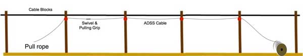 Installing ADSS Cable with the stationary reel method A pulling rope is attached to the cable with a swivel pulling eye and a wire grip. The cable reel should be placed well away from the first pole to prevent bending the cable excessively at the first pulley. The reel should have a brake to maintain significant tension as the cable is being pulled to prevent excess sagging between poles. The cable is positioned on the first pulley by a worker in a bucket truck or if the cable is low enough, by a worker on a ladder or using a special support pole. The cable is pulled by the pull rope while the worker in the bucket truck places the cable on the pulleys in sequence. Care should be taken to ensure the cable does not touch the ground and get dirty. A moving reel installation method can be done if there is a clear route for driving a vehicle with the reel of cable. A bucket truck follows to place the cable in the pulleys. Care must be taken to maintain the proper tension while paying off the cable from the reel. Once the entire cable has been pulled into place, the support hardware for each intermediate pole can be attached and the pulleys removed. At the ends of the section, the dead-end hardware is attached to the cable and the entire span is tensioned from one end. Since ADSS does not have a steel messenger, wind vibration can be a problem with the lightweight fiber optic cable. Wind vibration can cause degradation of the support hardware. Vibration dampers of several types can be installed to control wind vibration. At the ends of a section of cable where it is being spliced, the cable must be long enough to reach the splicing van or trailer plus about 5 m (16 feet) to allow for entry into the splicing van or trailer and have sufficient cable length for preparation and splicing. Dual dead-ends are used to secure the two cables meeting at the pole for splicing. All slack cable should be stored on cable storage brackets attached to the cables or the pole. Special fittings are available for slack storage and should be chosen for the location of the storage. Figure-8 Cable Figure-8 cable is an OSP cable with a messenger wire molded on the side of the cable. It is less commonly used for aerial installations but may be useful where no messenger is available. It is installed like a messenger wire but care must be taken to protect the fiber cable from damage. 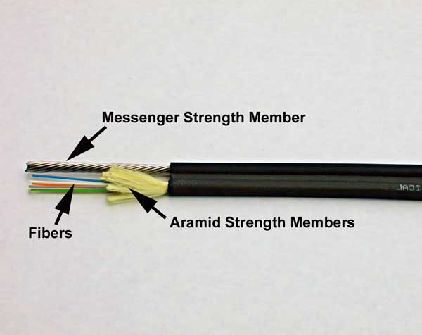 (C) 2018 The Fiber Optic Association Inc. Return to the OSP Construction Guide Index |
|
|